


An Axle for Front-wheel Drive
Page 70
If you've noticed an error in this article please click here to report it so we can fix it.
QOME front-wheel-drive arrange ments have a reduction gear fitted on the outside of the hub, but the extra space needed increases the overall width unduly. An improved layout in which the reduction gear is located between the two hub bearings, is shown in patent No. 721,784 (R. Cowell and Kirkstall Forge Engineering, Ltd., Leeds, 5).
Referring to the drawing, the driving shaft (I) is fitted with a pair of universal joints (2) centred on the axis of the steering trunnions (3). The drive then passes to a short shaft terminating in a sun-pinion (4). Stationary planets (5) transmit the drive to the outer annular gear (6) attached to the hub; this, of course, gives a reversal of drive. The patent is based on the fact that the epicyclic gear is placed between the bearings (7 and 8) which carry the hub, so that no extra width is demanded.
A BODYWORK DETAIL
PATENT No. 720,409 comes from F. Maddock and Weymann's, Ltd., of Station Road, Addlestone, Weybridge, Surrey, and shows a body-building refinement. In public service vehicles, it is often required to attach a panel parallel to, but spaced away from, another, and the patent shows a lightweight unit for use in this connection.
In the drawing, 1 is the T-member which carries the main panelling on its face (2). The secondary panelling (3) is required to be carried on the web of the T-member and the subject of the patent is the means adopted for its attachment, It consists of a sheet-metal strip (4) which is punched and bent at interv4als to form upstanding lugs (5). These are located on each side of the centreline alternately, thus leaving a space hetweeit them to suit the thickness of the web. The strip is attached by riveting to the web.
A useful property of the strip is that
it can be made in lengths and cut as desired. It can also be easily bent to follow any curved body contour.
A COMPACT FORK-TRUCK THE usefulness of I industrial powertrucks is greatly increased if they are able to manceuvre into confined spaces; a design, particularly good in this respect, is shown in patent No. 721,997 (F. Montgomery, 14 Ossington Street, London, W.1). The design also provides for easy removal of the driving unit if necessary.
Referring to the drawing, the truck is intended to be operated by a pedestrian driver and the controls are situated accordingly. The steering tiller (1) rotates the whole power-unit and transmission gear, both of which are contained within a cylindrical casing to allow of wide-angle turning. The unit revolves on a turn'table projecting from the main frame, and the single driving wheel is centred on the turning axis. • The tiller not only steers, but if moved downwards it engages the clutch, and if allowed to move upwards (by a spring) it applies the brake.
If space be unduly limited, the tiller can be swung upwards on hinge 2 by releasing a catch (3). The essential movements are then imparted by the driver grasping the upstanding handles (4).
The lifting mechanism is conventional in that a hydraulic ram (5), when extended, lifts the pallets via a speeddoubling pulley block.
THE POSITION OF SUPERCHARGERS
DATENT No. 722,028, comes from Daimler-Benz A.G., StuttgartUntertilatheim, Germany, and deals with the location of the supercharger of
a blown engine. The arrangement suggested is said to be equally suitable for carburetter-fed engines or those employing fuel injection.
The drawing shows a typical layout in which 1 is the carburetter and 2 the blower. In the case of a multicylindered engine, part 3 would be branched to form a manifold.
The basis of the patent is that the admission passage shall have a short downward inclination. The aim is to prevent the creation of eddies and oscillations in the gas flow.
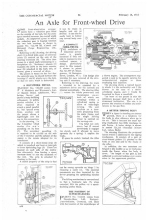
A BETTER TIPPING BODY
WHEN a tipper is standing on uneven YV ground, there is a tendency for the body to slew sideways when up in the air. This is because the usual tipping mechanism has little resistance to side forces. A better design is shown in patent 721,216 (Vauxhall Motors Ltd., Luton, Beds).
The drawing illustrates the proposed layout which is additional to the tipping mechanism. It consists of a pair of cross:braced girders (I), pivoted to the body at one end and to the frame at the other.
In addition, the two members are hinged in the middle so as to fold away inside the frame, when the body is down. The length of the pair is just sufficient to prevent locking over centre when in the uppermost position.