


Electric Drive to Tractor Front Wheels
Page 26
If you've noticed an error in this article please click here to report it so we can fix it.
ASCHEME for driving the front wheels of a tractor by electric power forms the subject of patent No. 610,501. which comes from W. Spence, 19, Kenilworth Road, Leamington; Warwickshire. The scheme is intended to replace track-layer drives, and provide equal adhesion.
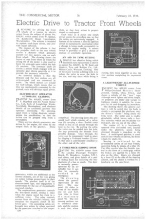
The essence of the scheme is that the propeller shaft to the rear wheels carries a dynamo which generates current for two motors, one on each front wheel. The ,drawing shows the layout of one front wheel in which the casing (1) of the motor is also used to form the stub-axle upon which the hub (2) revolves; The armature shaft (3) carries a pinion which engages with an epicyclic gear shown generally at 4 to provide the necessary reduction.
An essential feature is that the dynamo and -the two motors are all series-wound, and are connected in series. The wheel motors arc wound for half-voltage, which means that as they are mechanically connected by the ground, each will develop equal power.
ELECTRICALLY OPERATED AUTOMATIC GEARBOX
PATENT No. 610,633, comes from F. Highfield and the Austin Motor Co., Ltd., both of Longbridge Works, Northfield, Birmingham, and discloses details of an automatic gearbox that operates electrically. No drawing, apart from a wiring diagram, accompanies the specification, so that the action can be gasped only from a description.
There are two electric generators, one driven by the engine, the other by the output shaft of the gearbox. ,These
generators, which are additional to the normal dynamo, are of the type giving an output voltage proportional to their speeds. The gearbox itself is of the constant-mesh type, and engagement is achievement by the use of magnetically operated clutches.
The engine-driven generator controls the first-speed clutch; closing a relay when the engine speed has risen to a sufficient value. The relay controls current from the vehicle's battery, and energizes the magnetic clutch of the lowest gear. The succeeding ratios are brought into action by relays operated by the generator attached to the output
A38 shaft, so that their action is proportional to road-speed.
Each relay as it closes one clutch circuit opens the preceding one, so that the ratios are successively engaged. A feature of the scheme is that the ignition circuit is momentarily interrupted while a change is being made, presumably to prevent the engine racing. A master switch is provided to give a choice of manual or automatic operation.
AN AID TO TYRE FITTING
ASIMPLE but effective fitting which facilitates tyre replacement is shown in patent No. 610,391, by W. Scott and Henley's Tyre and Rubber Co., Ltd., Milton Court, Westcott, Dorking. One of the minor worries in fitting tyres is to induce the valve to enter the hole in the rim, and stay there while fitting is
completed. The drawing shows the proposed toot: which consists of a valvecap (1) carrying a short flexible cable which is first of all passed through the hole in the rim. By pulling the cable, the valve can be guided into the hole, the cap protecting the threads from possible damage. -Once through, the valve can be temporarily held in place by slipping a V-shaped washer (2) over it; this unit -is conveniently attached to the other end of the wire.
A THREE-PIECE SLIDING DOOR
PATENT No. 610,499 comes from the London Passenger Transport Board, 55, Broadway, London, S.W.1, and others, and gives details of a pair of sliding doors for enclosing the rear platform of a bus or coach. The door is normally poweroperated by an air cylinder but it can also be manually worked in an emergency.
• The drawing shows the general appearance of the door. The rear panel (1) slides in front of the middle one (2) and both then slide in front of a stationary panel f3). The two moving sections run in overhead channels, and the motion is such that, when A LIGHTWEIGHT ALL-PURPOSE VEHICLE
PATENT No. 609,501 comes from Willys-Overland Motors Incorporated, Toledo, Ohio, U.S.A., and shows a vehicle of the " jeep " type, although much lighter and more simple. Its purposes are many and varied; its lightness renders it suitable for trans. port by air and dropping by parachute.
The drawing shows the general outline; it will be noted that the body is simply a corrugated flat platform, only the driver's " cradle " being above the body level. The latter unit is readily detachable, which leaves only a boxlike structure which can be packed for transport, one on top of the other.
The engine (1) is a horizontally opposed twin air-cooled unit, located under the platform, access being obtained through a trap-door in the floor. A multi-speed gearbox is used, and all four wheels are driven, the front wheels by shafts (2).
Steering is achieved by the co-ordinated action of all four wheels, operation being by means of a tiller (3). The tiller carries also the throttle control in the form of a twist-grip, whilstthe brakes are applied by a lever (4) also on the tiller. Gears are changed by a lever (5) at the side of the steering column, and the clutch is worked by a hand-grip on the gear-lever.