


Hydraulically. Operated Stemless Valves
Page 36
If you've noticed an error in this article please click here to report it so we can fix it.
A Rdsurnd of Patent Specifications that Haile Recently Been Published
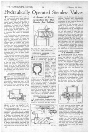
HE conventional.. valve, with its I comparatively small stem, is always on the border-line of suffering heat' damage, especially in these days of leaded petrol. Patent No. 557,815, by W. Smith, 180, Stratford Road, Birmingham, 11, deals with a stemless valve which, by reason of its design, is free from this disadvantage. This inventor goes farther than this, however, describing, in addition, a method Of operating the valve by hydraulic means.
In the drawing, 2 is a sliding valvebarrel having a normal type of conical seating surface where it meets the port (1). The barrel, being hollow, is light, whilst the bofe also forms a convenient space for housing the closing 3pring. For the purpose of hydraulic actuation, the 'barrel is enlarged at one end (4) into a piston-like head, which moves in a short cylinder. The annular space formed between the two diameters " acts as a pressure chamber for the hydraulic fluid, which is piped theretd via connection 3.
The hydraulic actuator (not shown) consists of four (for a lopr-cylindered engine) plungers each operated in Win by a rotating cam. •
An obvious advantage of the scheme is that the ports are unobstructed by stems and guides, so that the gas should have a free and open path. Unlike „...a poppet valve, however, this one is not self-sealing, bicaUse none of the prdjected area of the seating is open to gas pressure.
• COOLING SYSTEM FOR HYDRAULIC COUPLINGS . .
WHEN an hydraulic coupling is operating under cOnditions of considerable slip, all the wasted energy immediately appears as heat in the fluid, and may result in its temperature being raised to an undesirable, degree.. To minimize the risk of this is the
object of a sche,me shown in patent No. 558,061, by Borg and Beck Co., Ltd., and. D. Brock, both of Tachbrook Road, Leamington Spa,
The general principle is to allow the carburetter to take HS air supply through a casing surrounding the fluid -coupling. This gives the dual benefit of cooling the coupling, and, at the same time, warming the air supply. The drawing shews one way, of arranging the parts; in this case the air inlet (1) is on a short radius, so that the air is forced centrifugally outwards by vanes (2) on the rotary_member, finally travelling to the carburetter via pipe 3.
By using this air impeller, the engine is also given a slight supercharge. .
COMPOSITE LEATHER TYRE COVERS
AVAR-TIME substitute for rubber, \ . in the manufacture of tyres, is shown in patent No. 557,799, by B. Levy, 1-5, Osbert Street, London, S.W.]. This inventor proposes to construct the outer cover from leather, canvas and glue. Referring to the drawing, the innermost part is a layer of canvas (3), to which is glued an outer layer of thin leather. Thit-con.2posite member is doubled around the bead wires and brOughtt. to the Cater face of the tyre at point I. Latninated strips 'of leathef form the tread portion, • gaps being left, if desired; to create a patterned tread. Stouter rings of leather (4) form the side walls, all parts being united by glueing. As a further _ precaution, wire stitching is also provided, as shown at points 2 and 5.
• AIR HEATER FOR VEHICLE VENTILATION
AN exhaust heated air warming unit -and ifs associated controls form the subject of patent No."557,961, from R.
Stafford and R. Dutton, 37, Chestnut Avenue, Whitley Bay, Northumberland. The device is intended ler the ventilation of any type of vehicle on land or sea or in the air.
Referring to the drawing, the air enters (or is pumped in) via the inlet (7) and, after passing through an exhaust-jacketed coil (6), reaches pipe 5. Here it may pass up into a valve casing (2) and make its way into the vehicle, via connection 3. But if the slotted valve (1) be in such a position that pipe 5 is closed and pipe 8 open, then the incoming cold air will be directly diverted to the outlet (8). Intermediate positions of the valve (1) will, of course, give any desired mixture of hot and cold air. When in the "cold" position, a butterfly valve (4) is automatically opened; this permits the passage of a small airflow through the heater coil to prevent overheating.
, . ., •
MAINTAINING " OFF " PRESSURE . IN A BRAKING SYSTEM A" MODIFICATION, to a suctionassisted 'hydraulic braking system forms the subject of patent No. 557,762, _from Bendix. Aviation Corporation, . South _Bend, Indiana, U.S.A. The invention consists of a means for maintaining a slight " off " pressure in the pipe lines and wheel cylinders, but withholding this pressure from the valve that controls the
suction. •
Thedrawingshows the master cylinder; this has the usual reservoir (1) and..pedal-operated piston (2). In use, movement of the piston first forces a rubber-coned one-way valve (6) from its seating in its enclosing cup. Fluid thus passes to the brakes via pipe 5. On the return stroke, the oil cannot pass the .valve (6) and has, therefore, to lift it from its seating against the pressure of a light spring (3). The initial compression of this spring, therefore, governs the residual pressure, which is sufficient only to exclude air and to counteract gravity, effects if the vehicle be standing out a level.
The suction control "valve is also worked by the "pressure in the master cylinder, but the connecting pipe_(4) is taken from the other side of the valve (6), so that the residual pressure does not mach the amplifying system.