Patents Completed.
Page 20

If you've noticed an error in this article please click here to report it so we can fix it.
Sleeve-valve Cylinder-heads. New Sparking Plug. Two-cycle Valveless Engine.
Copies of complete specifications Of the patents published on this page can be obtained from the Sales Branch, Patent Office, Holborn, W.C., at the cost of sixpence for each specification.
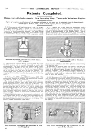
W. LANCHESTER and THE DADMLEH CO., LTD., No. 29,407, dated 20th December, 1913.—A simple and convenient form of building up a cylinder-head for a sleeve-valve engine is illustrated in the accompanying drawing. The head consists of two parts. The first is a plain outer sleeve which is made an accurate fit for the sleeve-valve which reciprocates outside it. The second is a funnel-shaped member which fits inside the first member and is centrally threaded to receive the sparking-plug. The outer edge of the funnel is fitted closely and welded to a shoulder on the first sleeve, and the sleeve itself is split at two points so that it can expand slightly on to the sleeve-valve and serve as its own packing. The cylinder-head when complete is .secured in place by a nut engaging the stern of the funnel on the outside, as the drawing shows.
E. W. COLE, No. 27,114, dated 25th November, 1913.—This specification describes a sparking plug and circuits arranged for a tell-tale spark on the dashboard.
The plug is arranged with two insulated contacts between which the spark normally takes place, these being connected to two insulated binding screws at the top of the plug. The lower end of the porcelain plug is forked and a contact point projects from each arm of the fork. A wire is wound round the plug near the root of the fork and is also laid in between two arms. This extra wire is connected to a third insulated wire within the plug which extends to near the top, where it, opens out into a recess; a. glass cover is fitted so that, this recess is visible.
If carbonizing takes place at the two main contacts, it will short-circuit either or both of them to the circumferential wire above them, and the current conducted to the upper end of the plug will spark across to the metal part of the plug. This spark is visible through the glass shield.
L. V. THOMAS, No. 19,908, dated 3rd September, 1913.— In this engine a pair of working cylinders constitutes a unit, and each cylinder has an annular pump chamber below it formed by an enlargement of the working piston. The ordinary arrangement of inlet and exhaust ports uncovered by the piston is used, and the mixture is supplied from a receiving
chamber on the right-hand side of the cylinders communicating with the inlet port.
A distributor is mounted below the receiver, and this controls the passage of the mixture into the two pumps, from which it is delivered again through the cifstributor to the receiving chamber. The distributor consists essentially of two piston valves, which are reciprocated by a rocking lever driven from a small crank on a transverse shaft, which is also used to drive the magneto.
W. IL HORSTMANN, No. 1570, dated 20th January, 1914.— The accompanying illustration shows the construction for a steering wheel. A stub-axle is mounted on a square bar which can slide vertically in the forks of the fixed axle. Attached to this bar is a lever which engages at its other end a rack also mounted on a fixed axle, and this lever is pivoted at the middle of an upwardly curved lever which is itself pivoted behind the vertically moving bar. This construction gives epicycloidal rolling movement to the lever, so that the bar carrying the stub-axle moves vertically without throwing any strain on its guides. The lever which is attached to this bar has two bosses, which are so positioned as to move horizontally when the bar is rocked, and compression springs are connected between these bosses and the fixed axle. Vertical movement of the wheel rocks the toothed lever and puts these springs under compression, so that vertical movements are absorbed by oppcsitely-direeted horizontal thrusts through the springs.


