


Rotary Valve Gear
Page 72
If you've noticed an error in this article please click here to report it so we can fix it.
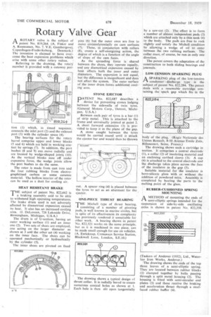
P-1 A ROTARY valve is the subject of patent No. 819,264. (A. Fisker and A. Rasmussen, No. 7. V.E. Gamborgsvej, Copenhagen-Frederiksberg, Denmark.) The invention is claimed to have overcome the heat expansion problems which arise with some other rotary valves. Referring to the drawing, the rotary member iS provided with a cutaway por
tion (1) which, in timed sequence, connects the inlet port (2) and the exhaust port (3) with the cylinder space (4).
The bearing surfaces for the rotary barrel comprise upper and lower blocks (5 and 6) which are held in working contact by springs (7). In addition, the port bushes (8 and '9) can move radially and are located by wedge-shaped joints (10). As the vertical blocks ease off under expansive force, the wedge joints allow the port bushes to do the same.
The rotor is made from cast iron and the four rubbing blocks from electrographitised carbon or some ceramic material. The hollow interior of the rotor can be used as a duct for cooling air.
HEAT RESISTANT BRAKE THE subject of patent No. 822,662 is a braking assembly said to be able to withstand high operating temperatures. The brake drum used is not adversely affected by diametrical expansion caused by heat. It also has an increased cooling area. (J. DeLorean, 726 Lakeside Drive, Birmingham, Michigan, U.S.A.) The drum is of U-section, having an outer working surface (1) and an inner one (2). Two sets of shoes are employed, one acting on the larger diameter as shown at 3 and the other set (4) working on the inner face. The shoes can be operated mechanically or hydraulically by the cylinder (5).
The inner shoes are pivoted on fixed pins (6) but the outer ones are free to move circumferentially on cam surfaces (7). These, in conjunction with rollers (8), create a self-energizing action, the degree of which is. a function of the angle of slope of the cam faces.
As the spreading force is shared between the shoes, they 'operate equally, and any diametrical expansion caused by heat affects both the inner and outer diameters. The expansion is not equal, but the difference is insignificant and does not affect the system. The outer surface of the inner drum forms additional cooling area.
STONE EJECTOR
DATENT No. 822,687 describes a
device for preventing stones lodging between the sidewalls of twin tyres. (General Motors Corp., Detroit, Michigan, U.S.A.) Between each pair of tyres is a bar (I) of strip metal. . This is attached to the frame and universally jointed at point 2. A short forward extension (3) is provided to keep it in the plane of the gap.
A stone caught between the tyres would be carried round until it struck the ejector bar and would then be thrown ONE-PIECE THRUST BEARING
THE Michell type of thrust bearing, consisting of a number of pivoting pads, is well known in marine circles, but in spite of its effectiveness its complexity has previously rendered it unsuitable for other work. A bearing shown in patent No. 822,321 works on the same principle, but as it is machined in one piece, can be made small enough for use on vehicles. (A. Enticknap, Crossways Service Station, Blackwall Lane, London, S.E.10.)
by a saw-cut (2). The effect is to form a number of almost independent pads (3) which are attached only by a thin neck (4) to the body. The pads are free to rock slightly and satisfy the Michell condition by allowing a wedge of oil to enter between the two rubbing surfaces. The collar must, of course, be run in only one direction.
The patent covers the adaptation of the construction to both sliding bearings and journals.
LOW-TENSION SPARKING PLUG
ASPARKING plug of the low-tension condenser discharge type , is the subject of patent No. 822.284. The patent deals With a renewable cartridge containing the spark gap which fits in the
body of the plug. (Regie Nationale des Usines Renault, 8-10 Avenue Emile Zola, Billancourt, Seine, France.) The drawing shows such a cartridge in section. It. comprises a central electrode (1), a collar (2) of insulating material and an enclosing earthed sleeve (3). A cap (4) is attached to the central electrode and the discharge takes place across the face of the insulator in the gap (5).
Suitable material for the insulator is boro-silicate glass with or without the addition of powdered mica. Assembly is completed by heating the parts to the melting point of the glass.
RUBBER-CUSHIONED SPRING MOUNTING
AMETHOD of mounting the ends of semi-elliptic springs intended for the suspension of side-by-side oscillating axles is shown in patent No. 822,350.