


Design for Pulverized-fuel Engine P ATENT No. 547,256,
Page 36
If you've noticed an error in this article please click here to report it so we can fix it.
' from D. Smith, Gramercy Tower, Dartmouth, and D. Kennedy, Harewood Forest, • Longparish, Hants, • deals with an engine using coal dust for fuel. As may be imagined, the chief problem with such an engine is the design of the fuel-admission mechanism, and the patent is concerned almost entirely with this aspect.
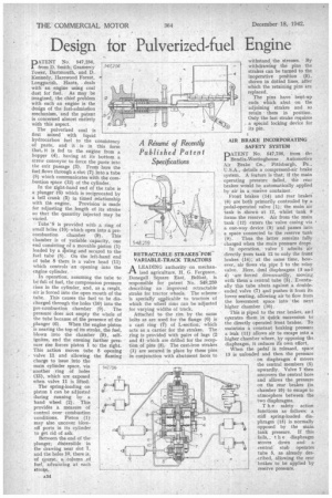
The pulverized coal is first mixed with liquid hydrocarbon fuel to the consistency of paste, and it is in this form that, it is fed to the engine from a hopper (4), having at its bottom a screw conveyor to force the paste into the exit passage (3). From here the fuel flows through a slot (7) into a tube (8) which communicates with the combustion space (12) of the cylinder. In the tight-hand end of the tube is a. plunger (6) which is reciprocated by a bell crank (5) in timed relationship with thh engine. Provision is made for adjusting the length of its stroke so that the quantity injected may be varied.
Tube '8 is provided with a ring of small holes (10). which open into a precombustion chamber (9). This chamber is of variable 'capacity, one end consisting of a movable piston (1) loaded by a epring and secured to the fuel tube (8). On the left-hand end of tube 8 there is a valve head (11) which controls an opening into the engine cylinder.
In operation, assuming the tube to ba•fuli of fuel, the compression pressure rises in the cylinder, and, as a resalt, air is forced into the open mouth of the tube. This causes the fuel to be discharged through the holes (10) into the pre.combustion chamber (9). The pressure does not empty the whole of the tube because of the presence of the
• plunger (6). When the engine piston is nearing the top of its stroke, the fuel, blown into the chamber (9), selfignites, and the ensuing further pressure rise forces piston 1 to the right. This action moves tube 8 opening • valve 11 and allowing the flaming charge to issue into the main cylinder space, via
• another ring of holes
• (13), which are exposed when valve 11 is lifted: The spring-loading on piston 1 can be adjusted during running by a hand wheel (2). This provides a measure of • control over combustion conditions. Piston (1). may also uncover blowoff ports in its cylinder to get rid of ash.
Between the end of the plungers discernible in the drawing near slot 7, and the holes 10, there is, of course, a column of fuel, advancing at each strok.e.
RETRACTABLE STRAKES—FORVARIABLE-TRACK TRACTORS A LEADING authority on mechan ized agriculture, H. G. Ferguson, Donegal! Square East, Belfast, is responsible for patent No 548,259 describing an improved retractable stmke for tractor wheels. The scheme is specially aAplicableto tractors of which the wheel rims can be adjusted for varying widths of track.
Attached to the rim by the same bolts as are used for the flange (6) is a cast ring (7) of L-section, which acts as a carrier for the strakes. The ring is provided with pairs of lugs (2 and 4)• which are drilled for the reception of pins (3). The cast-iron strakes (1) are secured in place by these pins in conjunction with abutment faces to withstand, the stresses. By withdrawing the pins the strakes can be turned to the inoperative position (5) , . shown in. dotted lines, after Which the retaining pins are . replaced.
The pins have bent-up ends Which abut on the adjoining strakes and so retain them in position. Only the last strake requires a special locking device for its pin.
BRAKE INCORPORATING SAFETY SYSTEM
DATENT No. 547,736, from the I Benclix-Westinghouse Automotive Air Brake Co., Pittsburgh, Pa.. U.S.A., details a compressed-air brake system. A feature is that, if the main operating pressure failed, the rear brakes would be automatically applied by air in a resei-ve container.
Front brakes (14) and rear brakes
(6) are both primarily controlled by a pedal-operated valve (I) ; the main air
tank is shown at 12, whilst •tank 9 forme the reserve. Air from the main tank (12) enters the valve casing via ' a one-way device (3) and passes into a space connected to the reserve tank (9). Thus the latter remains fully charged when the main pressure drops.
In operation, valve I admits air directly from tank 12 to only the front brakes (19); at the same time, how ever, air flows via pipe 2 to the relay valve. Here, dtral diaphragms (3 and
4) -Laze forced downwardly, moving with them a central tube (5) . Eventually this tube abuts against a double. ended valve (7) and pushes it from its lower seating, allowing air to flow from
the lowermost space" into the next • higher chamber (10).
This is piped to the rear brakes, and operates them in quick succession to
the directly operated front brakes. To maintain a constant braking pressure a leak (11) allows air to escape into a higher chamber where, by opposing the diaphragm. it reduces is own effort. When the pedal' is released, space. 13 is unloaded and then the pressure on diaphragm 4 moves
the central members (5) upwardly. Valve 7 then uncovers the central bore and allows the pressure on the rear brakes (in chamber 10) to escape to atmosphere between the two diaphragms.
T h e safety action functions as follows: a stiff spring-loaded diaphragm (15) is normally
opposed by the main tank pressure. If this fails„ t h e diaphragm moves down and a central. stub operates . tube 5, as already described, allowing the rear brakes to be applied by reserve pressure.