


Single Tread for Twin Tyres
Page 76
If you've noticed an error in this article please click here to report it so we can fix it.
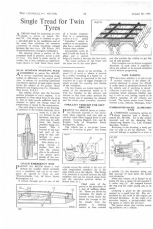
ATREAD band for mounting on twin wheels is shown in patent No. 866,779. The design is claimed to give a non-skid-grip in icy conditions and at the same time eliminate the common occurrence of stones becoming wedged between the two tyres. (W. Eckert, 10/2 Wiederholdstrasse, Stuttgart, Germany.)
The drawing shows a section of the proposed band in position across a pair of tyres. The band is made mainly of rubber, but it also contains an openwork tread (shown in thick black lines) made of a harder material. This is a proprietary substance called " Vulcollan " which, in addition to its hardness, also has a much higher friction than rubber.
Inextensible wires (I and 2) hold the band in place and a central bulge (3) locates it betweei the two tyres. The tread surfaces of the insert and the tyres are in the same plane.
DUAL IGNITION SPARKING PLUG A CCORDING to patent No. 868,687, ri in certain conditions sparking plugs reduce in efficiency as the engine speed rises. A scheme for providing additional non-electric ignition at high engine speeds forms the subject of the patent. (Esso Research and Engineering Co., Elizabeth, New Jersey, U.S.A.)
The scheme shown uses the hot-tube ignition principle of early engines. It is proposed to form blind bores in the plug so that at high speeds sufficient heat is retained to ignite the charge when its temperature is raised by the compression.
One such plug is shown in the drawing. In addition to the normal electrode, three bores (1, 2 and 3)
568,687 u,i are formed in the insulator. One bore alone may be sufficient, the lowest position being preferred. This is located in the hottest part of the plug so that selfignition is more readily created.
Also shown is a plug having a similar bore but with the volume able to be adjusted. The patent gives details of the preferred dimensions.
COACH EMERGENCY EXIT
PATENT No. 869,038 shows a roof fitment for coaches which normally carry a ventilator, but can in an emergency be opened to form an extt. (Weathershields. Ltd., 48 Moor Street, Birmingham, 4.)
A section through part of one of the ventilators is shown in the drawing. A panel (1) of metal or plastic is secured by a rubber moulding to a frame (2). A secondary frame is connected to the roof structure by a pair of toggle linkages (3) which provide for opening and closing of the ventilator.
The two frames are locked together by means of the mechanism shown at 4. This has handles on the exterior and interior so that from either position the main frame can if necessary be released and the whole panel assembly removed.
FORK-LIFT VEHICLES FOR SOFT GROUND
PATENT No. 868,033 shows an industrial lift-truck capable of fast movement when required, and also able to extricate itself when bogged down in soft ground. (Lansing Bagnall, Ltd., and R. Knights, both of Kingsclere Road, Basingstoke, Hants.)
The vehicle has a box-girder frame which is U-section in plan. The frame, extends across the vehicle at the rear (1) with longitudinal members (2) at the sides which carry the wheels. The lifting fork assembly is located between the side members and can be moved along them into the operative position shown in dotted lines at 3.
Chief point of the patent is the provision of a pair of walking plates (4). These are driven by zrankpins (5) which at bottom stroke lower the plates far enough to lift the wheels from the ground. A walking motion is thus created and this enables the vehicle to get itse out of soft ground.
The crankpins can be driven in opposit directions to each other if required t allow the vehicle to be turned completel round without progressing.
SAFE PASSING
TO determine whether it is safe to pa! another vehicle is the object of scheme disclosed in patent No. 871.64 A radar beam is projected forward fro; the vehicle and if anything is ahead reflection is sent back. This is fed into computer which indicates whether pas. ing is safe or not, having regard to th relative velocities of all vehicles cor 'cerned. The patent comes from Genera Motors Corp., Detroit, Michigan, U.S./
HYDRO-PNEUMATIC SUSPENS101 UNIT
I—I A COMBINED suspension spring an
shock absorber unit is shown i patent No. 867,500. Air is the resilier material and oil the damping fink (Armstrong Patents Co., Ltd., Eastgate Beverley, Yorks.) Referring to the drawing, a body pot tion (1) acts as an oil reservoir. Th external linkage is applied to a lever o a spindle (2), the direction being sue] that increase of load turns the spindl anti-clockwise.
When this Occurs, oil is forced by th piston (3) into a space (4) surrounded b. a rubber bag (5). Air trapped betweel the bag and the outer casing acts as th spring.
Damping is given by the restrictiol created by a small bore (6). The oil i throttled by this both in the impact am rebound directions. In the event of at excessive impact, a spring-loaded valv (7) opens to relieve the pressure.
The patent shows also various mount ing positions on a vehicle.