


Breakaway Trailer Brakes
Page 56
If you've noticed an error in this article please click here to report it so we can fix it.
A Risume of Recently Published Patent Specifications
PATENT No. 584,157, from the Clayton Dewandre Co., Ltd., and S. Willett, both of Titanic Works, Lincoln,
shows an air-braking scheme for trailers. The chief feature is that whilst the trailer brakes operate in unison with the brakes of the tractor, an accidental or intentional separation of the two vehicles will immediately apply the trailer brakes.
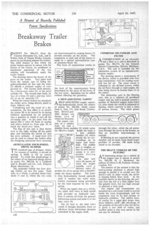
The drawing shows the layout of the parts on the trailer. Two pipes lead from the tractor, one (1) being the pedal-controlled air line and the other (2) affords a constant supply of com
pressed air. The former leads directly, via a throw-over valve (3), to the servo cylinder (4). The second pipe leads, by way. of a bore (5) and a one-way valve (6), to an air reservoir (7).
When the tractor brakes are energized, the trailer servo, being directly piped to them, follows suit.
Considering now the result of a disconnection, the first effect is to permit the piston (8) Co be moved by its spring (hitherto neutralized by air pressure) into a position in which it cuts off the air-supply pipe. At the same time the piston lifts a valve (9) from its seating and allows stored air, from pipe 10, to reach the throw-ovcr valve.
The flap of this unit is then blown over to the right, cutting off the pedal
pipe and directing the stored air into the servo cylinder. A hand lever (11) can be used to release the brakes after the foregoing operations have occurred.
ARTICULATED FOUR-WHEELDRIVE DUMPER THE standard type of dumper, which, for reasons of stability, is devoid of springs, is liable to tilt on uneven ground To avoid this disadvantage is the object of an improved design shown in patent No. 584,318, by J. Coldwell and E. Boydell and Co., Ltd., Elsinore Road, Manchester, 16.
The proposed vehicle has four driving wheels, on two live axles. Each axle, as a whole, is pivoted about trunnions (1 and 2), whilst the two axles are interconnected by rocking beams (3) pivoted centrally on the frame. The connection at each end of the beams is made by a special universal-joint type of plummer-block (4).
This form of construction results in the level of the superstructure being determined by the mean of the levels of the two axles. Springing can be added without affecting the geometry.
A SELF-ADJUSTING TAPPET
• A SELF-ADJUSTING tappet, operatt-1 Mg hydraulically, forms the subject of patent No. 584,302, which comes from L. Ord, 171, Arle Road, Cheltenham. Several pos sible designs are shown, o n e of which we illustrate.
The tappet consists of a tubular body (1) and a slidable thrust member (2) which varies the effective length. Inside the body is a free slidable member (3) which closely fits its surroundings on its upper and lower ends. The middle part is weighty, so that its own inertia causes it to reciprocate during running.
An inlet ball valve (4) passes oil when the weight ascends, and a delivery valve (5) permits the oil to escape into a chamber under the thrust member. The latter is thus hydraulically forced upwards until it reaches the valve stem, further movement being prevented. by the load imposed by the valve spring.
When the tappet rises as a whole, the upper ball valve is held closed and provides an hydraulic lock. Port 6 collects oil from the general lubricating system and leads it to the inlet valve (4).
The oil lead to the inlet valve could, if thought desirable, form an off-shoot from lubricating channels embodied in the tappet itself. COMBINED OIL-COOLER AND FILTER
ACOMBINATION of an oil-cooler and a filter as a unit is described in patent No. 584,174, by the General Motors Corporation, Detroit, Michigan, U.S.A. The unit is intended for the lubrication system of an internal-combustion engine.
The drawing shows a cross-secton of the device, which is provided with four pipe connections—two for cooling water and two for oil. The water circuit is indicated by the divided arrows, whilst the oil flows through at right-angles, the inlet being shown in broken lines (1) in the centre.
The interesting part is the filtering unit; this is a mixture of powdered copper and tin, and is packed around a number of flattened copper water-tubes (2), after which the whole is subjected to heating, which converts it into a mass of porous bronze. The water passes
through the tubes-, whilst the oil percolates through the pores in the bronze, so that an excellent heat-exchange is assured.
If filtering be not required, the porous member can be made from much larger particles of powder, 100 mesh being stated as an example.
THE HEAVY VEHICLE OF THE FUTURE?
AN interesting design for a vehicle of the largest type is shown in patent No. 584,230, by A. Marjeram, the address of whom is 48, Pulleyns Avenue, London, E.6.
The essence of the scheme is that the load-carrying platform is placed high enough to permit it to extend over the driver's cab; in other words, the driver is located below floor level. In the example shown in the drawing, the portion over the cab is a little higher than the general level, but not high enough to obstruct a long load.
The engine and transmission are mounted on a sub-frame which is carried inside the main Iongitudinals, and the suspension may be by leaf springs or hydraulic cylinders. The wheels must, of course, be a good deal larger than those hitherto used: An advantage of the position of the cab is that the driver is given a low field of vision, and another point is that easy access to the cab can be obtained.