


Patents Completed.
Page 20
If you've noticed an error in this article please click here to report it so we can fix it.
TREMBLER FOR INDUCTION COILS.—Guenet.—No. 27,974, dated 11th December, 1907.—The trembler comprises a flexible blade (a) having a platinum contact ; it is secured at one end to an iron plate (b), whilst its other end rests against the flange of a stop (c) secured to the end of the iron plate (b). The latter is supported and oscillates on another stop (d), and it is held in position by a spiral spring (e) provided with a tension screw (f). A platinum-tipped regulating screw (g) screwed into the bridge (j) corresponds to the platinum contact of the blade (a). On the current passing through the primary winding of the coil the plate (f') will be attracted by the magnetised core (k), and the shoulder of the column (c) will suddenly strike the end of the blade (a) and thus break the contact, whereupon the helical spring will bring the platinum pieces into contact again. A quick succession of closing and breaking actions on the primary circuit is thus produced, resulting in ignition sparks at the ends of the secondary circuit.
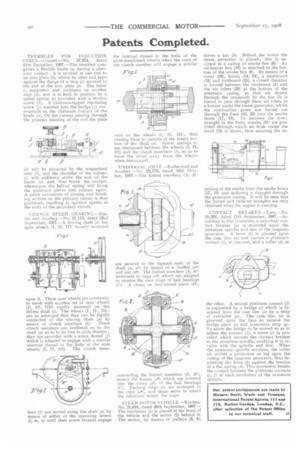
CHANGE SPEED GEARING.—Zimnic and Another.—No. 21,113, dated 23rd September, 1907.—A driving shaft (a) has spur wheels (I, II, III) loosely mounted
upon it. These spur wheels are constantly in mesh with another set of spur wheels (II, III, TIP) rigidly mounted on the driven shaft (e). The wheels (I., II., I1I.) are so arranged that they can be rigidly connected to the driving shaft (a) by means of clutch members (b). These clutch members are feathered on to the shaft (a) so as to be free to slide thereon ; they are provided with a screw thread (f) which is adapted to engage with a similar internal thread in the hubs of the spur wheels (I, II, III). The clutch mem bers (b) are moved along the shaft (a) by means of either of the operating levers (I, m, n) until their screw threads engage
the internal thread in the hubs of the afore-mentioned wheels when the cone of the clutch member will engage a similar
cone on the wheels (1, II, III), thus causing them to partake of the rotary motion of the shaft (al. Spiral springs (c) are interposed between the wheels (I, II, III) and the clutch members (b), so as to force the latter away from the wheels when disengaged.
UNIVERSAL JOINT.—Rutherford and Another.—No. 22,772, dated 16th October, 1907.—The forked members (A, Al)
are secured to the tapered ends of the shaft (a, al) by means of a feather (a5) and nut (a4). The forked members (A, Al) terminate in cups (a6) which are adapted to receive the race rings of ball bearings (C). A cross, or four-armed piece (D), connecting the forked members (A, Al), enters the bosses (a6) which are screwed into the cones (dl) of the ball bearings (C). Packing rings (e) are arranged in the cups (a6), and these serve to retain the lubricant within the cups.
STEAM MOTOR V E I II C LE.—Kitchen No. 21,616, dated 30th September, 1907.— The condenser (1) is placed at the front of the vehicle and the motor (2) behind it. The motor, by means of pulleys (3, 4), drives a fan (5). Behind the motor the steam generator is placed ; this is enclosed in a casing or smoke box (6). An oil-burner box (10) is attached to the bottom of the smoke box (6). By means of a cover (29), hoods (14, 24), a dashboard (13) and footboard (25), a closed chamber is formed between the condenser (1) and the air inlets (30) at the bottom of the generator casing, so that air drawn through the condenser by the fan (5) is forced to pass through these air inlets to a burner under the steam generator, whilst the combustion gases are forced out through the flues (22, 23) into the smoke boxes (17, 18). To increase the down draught in the flues, nozzles (31) are provided through which air from under the hood (24) is blown, thus assisting the ex
pelling of the smoke from the smoke boxes (17, 18) and inducing a draught through the generator casing. It will be seen that the forced and induced draughts are only obtained when -the engine is running.
CONTACT BREAKER.—Lutz.—No. 20,261, dated 11th September, 1907.—According to this invention, a cam-shaft contact breaker (a) is mounted upon tht. armature spindle and disc of the magneto generator. A lever (b) is pivoted upon the cam disc (a) and carries a platinum contact (c), at one end, and a roller (d) at the other. A second platinum contact (f) is supported by a bridge (e) which is insulated from the cam disc (a) by a strip of vulcanite (g). The cam disc (a) is grooved upon the face to receive -the bridge piece (e) and insulation strip (g). To allow the bridge to be moved so as to adjust the contact (f), a screw (i) is provided which secures the contact breaker to the armature spindle, enabling it to revolve with the spindle and disc. When the armature spindle revolves, the roller (d) strikes a projection or lug upon the casing of the magneto generator, thus depressing the lever (b) against the tension of a flat spring (Ix). This movement breaks the contact between the platinum contacts (c, fl at each revolution of the armature spindle.