


Replaceable Body Panels
Page 50
If you've noticed an error in this article please click here to report it so we can fix it.
BODY panels capable of being easily A Resume of Recently Published replaced, if eamaged, form the subject of patent No. 589,29, which comes Patent Specifications from A. Sainsbury and London Pas
senger Transport Board, 55, Broadway, London, S.W 1 In this scheme, the body pillars are secured to the cressmembers by bolts,' arid the panels are bolted to the pillars, so that detachment calls only for unbolting.
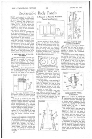
The drawing shows an exploded view of the, parts concerned. The pillar (1) is boltedto the cross-member (2), which also carries a dependent bracket (3) for the attachment of floor units (4).
The essence of the invention is the means for attaching the panels; these are fitted with weldel brackets (5) for the reception of bolts (n) which clamp two panels to the U-shaped upright. The edge-to,-edge joint between the two panels is sealed by inturned edges which sink into a rubber strip on the upright. Timber filling may be inserted in the hollow interior of the channel section.
A MAGNETICALLY OPERATED GEARBOX
A MAGNETICALLY operated gear11. box isprotected by patent No. 589015, • by C. Sewell and Lagonda, Ltd., Staines, Middlesex. The gearbox is the Cotal, and the patent deals mainly with a detail improvement in the construction.
The drawing shows the general outline, in which the input shaft (I) drives electro-magneticring • (2), •which forms the gin wheel of an epicyclic
tra n. The output shaft (3) is attached. to another magnet (4), which acts as the planet carrier of a second epicyclic gear.
A disc (5) is attached to the outer member of the first gear, whilst a second disc (6) is intagral with the sun wheel of the second epicyclic unit. The two central electro-magnets (7) are attached to the casing by a method which allows accurate spacing by means of shims.
By selectively energizing one or another oi the four magnets, a range of ratios can be obtained, without the need for further clutching arrangements TELESCOPIC REFUSE COLLECTOR
A REFUSE collector in which the rtbody moves with a teleseopic action is the subject of patentNo. 589,306; by Walker Bros. (Wigan), Ltd., and T. Dunstan, both of Pagefield Iron Works, Wigan, Lancs. The body motion can be used for packing the load and for moving it to the rear in readiness for discharge.
A40 The rear section (1) of the body is a fixture. All the other sections (2) can be slid one within the next, so that they can all be accommodated in the rear unit. The motive unit is a telescopic hydraulic ram (3), which works in either direction, according to whether the body is required to open or shut. The outline of the body, as viewed from the rear, is approximately semi-circular. • TYRE CHAINS FOR TWIN AXLES
PATENT = No. 589,200, from E. Dennison, Westbourne, Goodworth. Clatford, Andover, Hants, deals with chains for increasing the road grip of multi-axled vehicles, particularly those using large tyres.
The main feature is the provision of long side-flaps on the chains so as effectively to embrace the tyre as they approach it. The chain is composed of rigid cross-bars pivoted to the sideflaps (I) about axes (2), the whole being connected by chain links.
A feature of the patent is that adjacent links are connected at different heights on the side-flaps (compare 3 and 4) so that only half the number meet the tyre at first, the remainder then settling down without rubbing action.
GENERAL-PURPt 'ISE SELFALIGNING BEARING AN inexpensive self-aligning bearing which may be used to attach a variety -of units to a chassis frame is covered by patent No. 589,417, by Thompson Products' Inc., Cleveland, Ohio, U.S.A.
The drawing sb.:iws its use as part of the Steering mechanism. The shaft (1) carrying the arm (2) has its axis positioned by external considerations, but it is desired to bolt it to the frame through lugs (3). The shaft runs in a sleeve (4) carried by a semi-ball joint, which gives freedom of angle. The bag joint is spring-ioaded to-take up wear, and is provided with rubber sealing washers (5) at both ends.
TESTING FRONT-WHEEL ALIGNMENT 'THE usual methods of aligning the front wheels of a vehicle can hardly be classed as precision operations, and to obtain greater accuracy in this respect is the aim of apparatus covered by patent No. 589,362, by F. Carr and Dunlop Rubber Co., Ltd., I, Albany Street, London, N.W.1.
The drawing shows a plan view of the apparatus in position about a pair of wheels (1). Each of two units is mounted on castors and can be pulled into contact with the wheel rims by spring-loaded bands, not shown. Two fingers (2) fc rm the rim-contacting members.
This action lines up each unit parallel to one wheel; the operator then looks through an eyepiece (3) and swivels it until its reflection is visible in a mirror (4). The angle of deflection can then be directly read off a calibrated scale (5), which indicates both the error and its direction.