


The Specification and Testing of Motorcar
Page 15
Page 16
Page 17
If you've noticed an error in this article please click here to report it so we can fix it.
Steels.
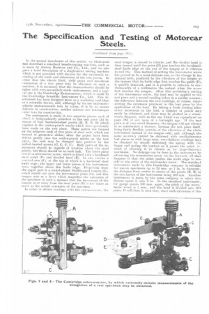
In the second instalment of this article, we illustrated and described a standard tensile-testing machine, such as is made by Joshua Bucktcm and Co., Ltd., and we also gave a brief de.scription of a single-lever testing machine which is not provided with devices for the automatic recording of the loads and extensions of the test pieces. In order that the elastic limit, yield point and maximum extensions of a test piece may he obtained on such a machine, it is necessary that the measurements should be taken with very-accurately-made instruments, and a typieal one is the Cambridge Extensometer, which is made by the Cambridge Scientific Instrument Co., Ltd. This instrument has been designed more as a workshop tool than as a scientific device, and, although by its use extremelyminute measurements may be taken, it is by no means delicate in construction ; neither mirrors nor microscopes enter into its construction.
The instrument is made in two separate pieces, each of hieh is independently attached to the test piece (A) by means of four hardened-steel points (B, B, 13 B) which register in the centre-punch marks which have previously been made on the test piece. These points are formed on the adjacent ends of two pairs of steel rods, which are housed in geometric slides; after the points have been driven gently into the centre-punch marks on the test piece, the rods may he clamped into position by the milled-headed screws (0, C, C, C). Both parts of the instruniont should he capable of rotation about the steel points, but there should be no back lash. The lower piece carries a micrometer screw, which is fitted with a hardened steel point (Di and divided bead (E). It also carries a vertical arm (F), at the top of which is a hardened steel knife edge; the upper and lower pieces of the instrument work together about this knife edge. Projecting from the upper part is a nickel-plated flexible-steel tongue (0), which stands out over the micrometer point (D), and this tongue acts as a lever which magnifies the extension of the specimen in such a manner that the mevement of the tongue to or away from the steel point (D) is live times as much as the actual extension of the specimen. In order to obtain readings with the extenseineter, the
steel tongue is caused to vibrate, and the divided head is then turned until the point (D) just touches the hardenedsteel knife edge on the end of the tongue as it. vibrates to and fro. This method of setting the micrometer screw has proved to be a most-delicate one, as the change in the musical note, produced by the vibration of the tongue at the instant that its knife edge first touches the point (D), is quickly detected, and it is possible to indicate to onethousandth of a millimetre the instant when the screw first touches the tongue. After this preliminary setting of the micrometer screw, the load may be applied to the test piece and a second reading taken in a similar manner, the difference between the two readings, of course, representing the extension produced in the test piece by the application of the. load. By taking a fresh reading after every increment in the load, a number of points may easily be obtained, and these may be plotted as a stressstrain diagram, such as the one which was reproduced on page 183 of our issue of a fortnight ago. If the test piece is of very-small diameter, the tongue will not vibrate in so satisfactory a manner, because the test pieve being fairly flexible, permits of the vibrai ion of the whole instrument instead of the tongue only, and, although the same accuracy cannot be obtained with small-diameter test pieces as with large ones, very-delicate readings may he obtained by simply deflecting the spring with the finger and noting the contact as it passes the point, instead of allowing it to vibrate as for large-tliameter specimens. No damage can be done to the instrument by advancing the micrometer screw too far forward ; all that happens is that the point pushes the knife edge to miss side or the other of the micrometer screw. Th,, standard instrument made by this Cambridge company is suitable for use on specimens up to 20 mm. or 1in. in diameter, he distance from centre to centre of the points (B, B) in the two halves of the instrument being 100 min. Another instrument is made by the same company in which this distanc apart is only 2 in. In the standard instrument_ for gauge points 100 mm. apart, the pitch of the micrometer screw is !, mm., and the head is divided into 10() parts. It will thus be seen that., since each extension of the
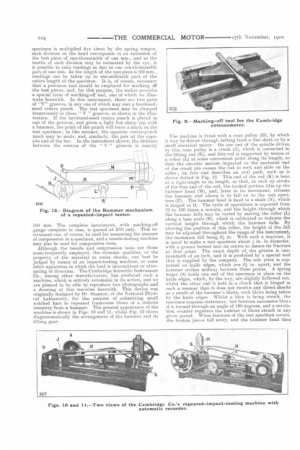
specimen is multiplied five times by the spring tongue, each division on the head corresponds to an extension of the test piece of one-thouSandth of one mm., and as the tenths of each division may be estimated by the eye, it is possible to take readings so fine as one ten-thousandth part of one mm. As the length of the test piece is 100 mm., readings can be taken up to one-millionth part of the entire length of the specimen. It is, of course, necessary that a precision tool should be employed for marking off the test pieces, and, for this purpose, the maker provides a special form of marking-off tool, one of which we illustrate herewith. In this instrument, there are two pairs of "V" grooves, in any one of which may rest a hardenedsteel centre punch. The test specimen may be clamped transversely to these " V " grooves, as shown in the illustration. If the hardened-steel centre punch is placed in one of the grooves, and given a light but sharp tap with a hammer, the point of the punch will leave a mark on the test specimen; in like manner, the opposite centre-punch mark may be made, and, similarly, the pair at the opposite end of the bar. In the instrument shown, the distance between the centres of the " V " grooves is exactly 100 mm. The complete instrument, with marking-off gauge complete in case, is quoted at £10 only. This instrument can, of course, be used for measuring the amount of compression in a specimen, and a tensile-testing machine may also be used for compressive tests. Although the tensile and compression tests are those most-frequently employed, the dynamic qualities, or the property of the material to resist shocks, can best be judged by means of an impact-testing machine, or some other apparatus in which the load is intermittent or alternating in direction. The Cambridge Scientific Instrument Co., among other manufacturers, has produced such a machine, which is entirely automatic in its action, and we are pleased to be able to reproduce two photographs and a drawing of this machine herewith. This device was originally designed by Dr. Stanton, of the National Physical Laboratory, for the purpose of submitting small notched bars to repeated transverse blows of a definite intensity from a hammer. The general appearance of the machine is shown in Figs. 10 and 11, whilst Fig. 12 shows diagrammatically the arrangement of the hammer and its lifting gear.
The machine is fitted with a cone pulley (k1), by which it may be driven through belting from a line shaft or by a small electrical motor. On one end of the spindle driven by this cone pulley is a crank (J), which is connected to the lifting rod (K), and this rod is supported by means of a roller (L) at some convenient point along its length, so that the circular motion imparted to the anchored end of the crank pin causes the rod to rock and slide on the roller; its free end describes an oval path, such as is shown dotted in Fig. 12. This end of the rod (K) is bent at a right-angle to its length, so that, at each up stroke of the free end of the rod, the hooked portion lifts up the hammer head (M), and, later in its movement, releases the hammer and allows it to fall on to the test. specimen (P). The hammer head is fixed to a shaft (N), which is hinged at 0. The cycle of operations is repeated from 70 to 100 times a minute, and the height through which the hammer falls may be varied by moving the roller (L) along a base scale (It), which is calibrated to indicate the vertical height through which the hammer falls. By altering the position of this roller, the height of the fall may he adjusted throughout the range of the instrument, the maximum fall being 3.1 in. With such a machine, it is usual to make a. test specimen about in. in diameter, with a groove turned into its centre to insure its fracture at that point. The exact depth ofi the groove is onetwentieth of an inch, and it is produced by a special tool that is supplied by the company. The test piece is supported on knife edges, which are 4i in. apart, and the hammer strikes midway between these points. A spring finger (5) holds one end of the specimen in place on the knife edges, which, by the way, are slightly hollowed out, whilst the other end is held in a chuck that is hinged in such a manner that it does not receive any direct shocks as a result of the hammer's blows, such blows being taken by the knife edges. Whilst a blow is being struck, the specimen remains stationary, but between successive blows it is turned through an angle of 180 degrees, and a revolution counter registers the number of blows struck in any given period. When fracture of the test specimen occurs, the broken pieces fall away, and the hammer head then
trips an electric switch which should be connected to the circuit of the driving motor so that the machine may very quickly be brought to rest.
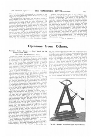
The calculation of the force of the blow may readily he made, and the figures thus obtained be compared with the results derived from tests on other specimens. The material for such parts as axles, steering gear, transmission shafts, gears, and other details which are called upon to sustain shack in a motor vehicle, should be tested in a machine of this class in preference, or in addition, to a tensile-testing machine. Some of the advantages of repeated-impact-testing machines arc; (I) that the specimen is subjected to a simple and sudden stress whieh is frequently reversed and is of a calculable amount ; (2) that the machine, having once been set up, may be run without further attention ; (3) the force and frequency of the blows may easily be adjusted; and (4) the number of blows struck may automatically be recorded throughout the test. Another form of impact tester is the pendulum type, such as is made by W. and T. Avery, Ltd., of the Soho Foundry, Birmingham. The design of this machine, as may be seen from Fig. 13, is extremely simple. It consists of a weighted pendulum which is raised to a certain height and allowed to swing and strike the test piece. The number of foot pounds of energy which a test piece has absorbed in resisting the falling pendulum is automatically registered on an indicating quadrant by the finger shown in the illustration. The striking point of the pendulum is at, the centre of the test piece, and the whole of the energy of the falling weight is transmitted to the specimen. The point of contact of the falling weight is protected from wear and injury by the provision of 41, hardened-steel knife edge. The pendulum itself is fulcrumed on to hardened-steel cones, one of which is adjustable for wear.