


A Stabilizer for Large Vehicles
Page 60
If you've noticed an error in this article please click here to report it so we can fix it.
pATENT No. 728,397 (Daimler-Benz A.G., Stuttgart Unterturkheim, Germany) discloses a means for interconnecting the springs. on each side of a vehicle so that • an upward force
applied to one side meets a greater resistance than if it were applied to both sides. The scheme is said to be suitable for buses and similar large vehicles, particularly those in which the springs are located well inboard.
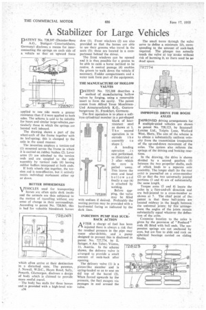
The drawing shows a part of the wheel-arch of the frame together' with its leaf-spring; this is clamped to the axle in the usual manner.
The invention employs a torsion-rod (1) mounted across the frame in which it is carried on rubber bushes (2). Lever arms (3) are attached to the torsion rods and are coupled to the axle assembly by vertical rods ' (4) having rubber buffers interposed at both ends.
If both wheels rise together, the torsion rod is non-effective, but it actively resists individual movement either up or down.
BETTER HORSEBOXES
VEHICLES used for transporting horses are often quite dark inside and the animals are thus subjected to the motion of travelling without any sense of change in their surroundings. According to patent No. 728,063, this is bad for valuable bloodstock horses which often arrive at their destination in a disturbed state. The patentee, J. Nowell, W.D.C., Hayes Road, Sully, Penarth, Glamorgan, discloses a design of body which is claimed to provide
more restful -travel. • The body has stalls for three horses and is provided with a high-level winA34 dow (1). Front windows (2) are also provided so that the horses are able to see their grooms who travel in the seats (3); these are located in a compartment behind the driver.
The front windows can be opened and it is thus possible for a groom to be able to calm a horse inclined to be restive. A central passage (4) enables the groom to walk down the vehicle if necessary. Fodder compartments and a water tank form part of the equipment.
THE MANUFACTURE OF HOLLOW VALVES
PATENT No. 725,208 describes a method of manufacturing hollow valves by forging, using a removable insert to form the cavity. The patent comes from Alfred Teves MaschinenUnd Armaturenfabrik KG., Gustavsburgstrasse 31, Frankfurt, Germany.
The first operation is to place a softiron cylindrical member in a pot-shaped blank of heatresistant steel as shown at 1. The second operation is to extrude t h e assembly 1 o shape 2.
A heading operation i s next performed, as illustrated at 3 after which the core is pulled away. This leaves the stem and head hollow and finally a cap (4) is attached by welding.
Before capping, the valve may be filled with sodium if desired. Preferably the seating portion may be provided with a hard-metal facing as indicated by the dark lines.
INJECTION PUMP HAS SUCKBACK ACTION AFTER a charge of fuel has been injected there is always a risk that the residual pressure in the pipe may cause after-dribble, and a pump designed to prevent this is disclosed in patent No. 727,774, by E. Satzger, 6 Am Tabor, Vienna, 11, Austria. In the scheme shown, the delivery valve is arranged to provide a small amount of suck-back after opening.
The delivery valve (I) is a piston-like member and is spring-loaded so as to seat on the top of the barrel (2). When forced upwards by the pressure, the fuel escapes via passages in and around the valve.
The small bores through the valve serve to define a minimum lift, corresponding to the amount of suck-back required. The plunger can actually touch the valve at top stroke without risk of harming it, so there need be no dead space.
IMPROVED DRIVE FOR BOGIE AXLES IMPROVED driving arrangements for I multiple-axled vehicles are shown in patent No. 728,123, by Scammell Lorries Ltd., Tolpits Lane, Watford West, Herts./The aim of the scheme is to obtain a substantially uniform velocity from the transmission irrespective of the up-and-down movement of the axles. The system also relieves the springs of the driving and braking reactions.
In the drawing, the drive is shown divided by a second gearbox (1) between the two ,propeller shafts, each of which leads to a separate axle assembly. The longer shaft (to the rear axle) is journalled on a cross-member (2) so that the two universally jointed portions (3 and 4) are of substantially the same length.
Torque arms (5 and 6) locate the axles in a fore-and-aft direction and are ball-jointed to a cross-member as shown at 7. The chief point of the patent is that these ball-joints are located midway in the length between the universal joints; by this arrangement the angles of the joints remain substantially equal whatever the deflection of the axles.
Crosswise location to the axles is given by the provision of " Panhard " rods (8) fitted with ball ends. The suspension springs are not anchored by eyes, but are free to slide and rock on spherical bearings carried on sliding blocks.