


VARIABLE COMPRESSION.
Page 30
If you've noticed an error in this article please click here to report it so we can fix it.
A Résumé of Recently Published Patent Specifications.
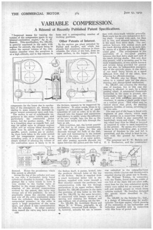
"Improved means for varying the volume of the compression space in any internal-combustion engine," by A. N. Barrett. This specification, No. 126,155, is actually concerned in the main with engines for aircraft, the object being to reduce the normal volume of the combustion chamber when the aeroplane is at a high altitude, and in this manner to
compensate for the losses due to rarefaction of the atmospheric air, thereby obviating to some extent the decrease in. power output consequent upon such loss. '
The matter is one a considerable importance to the motor vehicle user, and particularly the commercial motor owner, but for another reason.. We are in a transition stage as regards fuel, and may be called upon to prepare enginei which will at various times throughout their lives be called upon to consume paraffin, petrol, suction gas or alcohol. As these fiiels taken in the order named call for compression' pressures in an ascending scale, it is evident that some simple method of altering the volume of the combustion space is likely to be in
demand. Hence the prominence which this patent is afforded.
Across the top of the cylinder and near to one side, a horizontal, truly bored cylindrical chamber is formed. Into this passage fits a valve which in form is very similar to the Corliss valve so familiar to the steam engineer. In the simplest of the several constructions covered by the patent, this valve may occupy one of two positions. In one it practically closes the circular passage and cuts off the extra combustion space from the cylinders, thus increasing the compression pressure; in the other it opens a large proportion of the extra space, and places it into communication with the cylinder. In .other constructions named the valve may have several C58 faces and a corresponding number of working positions.
Other Patents of Interest.
In. the suction gas plant patented by Parker and another, and which has already had occasional reference in these columns, the whole of the fuel, from its upper surface, in the hopper, down to
the firebars, appears to be supported by the firebars. In other words, there is no regular or intermittent feed of small quantities of coal or coke; it is all discharged into the hopper and commences iminzdiately to settle under the influence -of its own weight; into the fire as the lowest layer burns and falls through the
bars as ash. '
Only a portion, say, the lowest quarter of the fuel is, of course, incandescent, and the delivery pipe for the gas descends through the bulk of the fuel, its open end terminating in the hottest portion of the mass. Air enters the producer at the bottom of an outer jacket, . and after passing upwards through the space between the jacket and the wall of.
the firebox itself, it passes, heated, into the producer through holes at the top of the firebox. Steam is supplied from a small horizontal bOiler laid in the firebars, supplied with water through a float chamber outside the producer, and communicating with the fire through perforations in its upper 'surface. Specification No. 126,140 concerns in the main the provision of this boiler in the fire, and No. 126,172, by the same inventor, is concerned with simple means of removing and cleaning the firebars and pan without risk of putting out the fire.
No. 126,208, Sir Archibald Moore and Major W. G. Wilson, originally, in all probability, concerned Tankdesign. It is, however, suitable for use in connec
tion with chain-track vehicles generally. Each track has its own independent driving shaft. Co-axial with each, for they are in line, and situated between them, is the main final drive shaft. The connection between this central shaft and the track driving shafts is, in each case, by means of a double epicyclic or differ ential gear. The arrangement is the equivalent of a two-speed gearbox between the final drive shaft and each of the track driving shafts. Not only does this permit, with a reversing gear in the main transmission, of two speeds forward and reverse being provided for general
use, but also, by independent manipulation of the epicyclic gears, it also allows of onetrack being driven at a speed different from that of the other, thus allowing for efficient steering.
No. 126,032, also by Major Wilson, refers to a control gear for the above steering and change-speed mechanism. No. 126,017, also concerns the steering gear of tractors but in this case the
steering -is effected, in part, by a front
guiding wheel. A substantial framework horizontal in the main is pivoted, :elan
horizontally, near its .ear end. At the
front, and with adequate provision for clearance it carries a single guide wheel on a vertical pivot. This wheel may be turned -about that pivot, for steering purposes, besides, of course, revolving on its own axle.
The rear end of the beam is fitted with segments of. gear wheels, which mesh with pinions on a transverse strap, the motion of which is also controlled by handwheel, worm and wheel. The steer ing. wheel may thus be lifted or lowered as required in order to meet inequalities in the ground. By means of a freewheel device in the controlling gear, a certain amount of freedom to rise and fall is permitted, and the wheel is kept in contact with the ground by means of springs. The patentees are P. W. Robson and F. J. Bretherton, and the constructioe was embodied in the caterpillar-type tractors which Clayton and Shuttleworth supplied during the great war to Russia. , Sir William Tritton, in 'connection with the Tanks, found that the width of one link of the chain did not allow auffi-t cient base for the very substantial anus% which were called for 011 account of the soft and muddy ground on which thosevehicles worked. lie therefore designect the special biters described in No. 126,079.
No. 126,037, by the Daimler Co., Ltd.y• is a design of induction pipe for multicylinder Vee-type engine, which permits of the utilization of one carburetter and 'induction manifold' only in connection with this form of'power unit.