


Finding Room For Large Valves
Page 58
If you've noticed an error in this article please click here to report it so we can fix it.
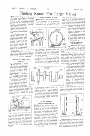
THE engine designer is always up against the problem of providing large valves within a limited area and a possible solution is disclosed in patent No. 698,659, by Daimler-Benz .A.G.,
Stuttgart Untertiirkbeirn. Germany. Extra cylinder-head area is obtained in two ways, one being to slope the head at an angle, and the other by encroaching on the cylinder wall.
The drawing shows the angle of slope, also the part of the combustion space penetrating into the cylinder wall in the vicinity of the sparking plug. In the example shown, the lefthand valve is the inlet, but the exhaust valve may alternatively be placed Here, where it is protected to some extent from the flame.
Although the valves are placed at an angle to the cylinder, they are perpendicular to the underside of the head, a feature which facilitates machining.
ROLLER-BEARING MAIN JOURNALS
A CRANKSHAFT, having Pi, large web discs carrying roller bearings and claimed to possess extraordinary rigidity, forms the subject of patent No. 692,517, which comes from K. Maybach, 21 Zeppclinstrasse, Friedrichshafen, Bodensee, .Germany. It is intended for the larger sizes of vehicle engine, including those for railcars, The drawing shows part of a six-cylinder shaft according to the invention. It will be seen that the inner roller races (1) are integral with the shaft and provided with roller retaining flanges. The bearing surfaces and the inside of the flanges are hardened, preferably by the induction-heating process to avoid distortion.
One complete bearing is shown at 2 Clued into the crankcase. Having the flanges on the inner race enables the nearing to throw out any particles of mrbon and other foreign bodies from the outer plain ring. The crankcase need not be split, as the large housing enables the shaft to be inserted from one end, A40
A TYRE WITHOUT A TUBE PATENT No. 692,019 shows a tubeless pneumatic tyre in which the cover forms the air chamber. The advantage is that the scheme abolishes
the numerous troubles caused by chafing of the cords of the outer cover by rubbing of the tube. The patentee is J. Servaes, 36 Boulevarde Poincare a Bruxelles, Belgium.
The outer cover is substantially normal, all that is different being the provision of a soft rubber ring (I) round the rim. The drawing shows the tyre in the process of inflation, in which
air entering the valve (2) lifts the ring slightly and allows the air to reach the interior via hole 3. When inflation is completed, the ring is forced down flat on to the rim and forms a seal over the whole surface, including the lips (4) which are firmly nipped between the cover bead and the rim.
AN OIL ENGINE COMBUSTION SYSTEM
DATENT No. 691.932. shows com
bustion arrangements for oil erigines, claimed to give a high performance over a wide range of speed. to facilitate starting and to give smokeless running. The patentee is Daimler-Benz A.G., Stuttgart-Untertarkheim. Germany.
The piston is provided with a shallow depression (1) which forms the main compression space. As top dead centre is approached on the compression stroke, the air is squeezed out from above the flat portion of the piston and travels radially inwards, thus creating an annular swirl. The throat (2) of the pre-combustion chamber (3) is directed towards the centre of the swirl, and at starting, some of the fuel can penetrate down to piston level, where the air is hottest. It is this feature that 'helps in easy starting. At high speeds, there is not time enough for this to occur, and the combustion is initiated in the spherical chamber.
To assist the maintenance of a high temperature in the pre-combustion chamber, it is lined with some heatinsulating material.
RAPID WASHING OF VEHICLES
A MACHINE for rapidly
washing a bus is shown in patent No. 692,005, by R. Cox, 229 Broadway North, Walsall, Staffs.
The machine comprises a pair of upstanding pillars (I). having a vertical shaft running for the full height. The shaft carries sets of bristles (2), so staggered that only half of them touch the vehicle at any moment. The shaft is rotated by an electric motor (3) and reduction gear. A copious water supply is piped on to the brushes, and an enclosing guard round the brushes prevents splash.
Each unit is mounted on castors guided by rails (4) so that it can be adjusted for different widths of vehicle, and the uprights can be inclined at an angle to accommodate vehicles with sloping sides. In operation the vehicle is slowly driven through the working unit, the drainage being collected by gullies (5).
By taking one of the.units off i s rails it can be moved on its castors and used to wash the back or front of a vehicle.
An attraction of this particular design of vehicle washer lies in its mobility. Wien the vehicles have been washed the units can be removed to leave available the space that would be absor..ed by a permanently sited washer.