


HYDRAULIC TRANSMISSION.
Page 28
If you've noticed an error in this article please click here to report it so we can fix it.
A Résumé of Recently Published Patents.
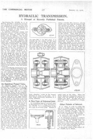
Specification No. 157,979, by A. G. Michell, describes a hydraulic transmis sires, which is, as a matter of fact, actually designed for use in connection with boats. It is, ■however, of, sufficient interest to readers of' this journal to justify brief reference here.
It embodies con-Snifugal pumps and hydraulic•turbines. As shown in the accompanyingdrawing, there are two pumps an' one turbine. The former sre engine driven and revolve its an antislockvvirse direction; they deliver water to the turbine, which operates the iriven shaft. Both The pumps and the :urbine are mounted within a common :asing whkh is fluid filled. The turbine, s a -dual one, 'having one main set of lades to which water is admitted in -he middle of the rim, making its exit Ittthe centre. The other portion conists of short blades mounted, as it vere, at the corners of the turbine; hey also accept the water at the rim ,ad allow it to pass away at a point ',serer the centre but actually outside he body of the main turbine. A set of rates is provided • to divert the water .
rona the pumps either to the main perion of the turbine, in which case 'the oat or vehicle is driven in a forward lirection, or to direct it to the auxiliary antion of the turbine, when the motion s reversed.
A second hydraulic transmission is the abject of No. 172,976 by J. Giard. This of somewhat ,complicated construeion, but embodiesthe familiar prins
iple of awash-plate jnechanism for conrolling the stroke, of .the pumps and ydranlic. motors, whereby different peed, ratios between' drive' andshafts say be effected. A special feature, or his conueructiou is the arrangement of fiction clutches.
An Ingenious Poppet" Valve.
An ingenious poppet valve, is deerilsed in No. 172,0719 by L. -W. Bremer!' 'he. valve has a loose head, formedeof heet metal, in two parts.The valve tern, at its upper end, has a hemipherical knob which, on its underside, ears in a corresponding Concave formaion of the sheet-metal head This head hollow and has.a• fiat upper portion 7hic,h, in normal circumstances, presses pOn the head of the valve stem, and ceps its hemispherical portion in close ontact with the concave part of the alve head itself. In this flat 'top are a unbar of holes, and advantageis aken of this construction, particularly connection with exhausts' valves, to emove the pressure upon the valve at. he commencement of us opening. It perates thus when the stem corniences to lift, the-flat; upper portion of he valve flexes under the pressure, and' Bows the knob of the stem to comei way from its seat inside the head The xhaust gazes may then pass' through he holes-in the flat, upper portion of he valve head, between the knob of the tom and the concave portion of the sad, -and thus to the manifold. Another iature of the valve, is that it is con
's.eing turned upon its seat, each' ime it re-seats itself after having penesl This is due to tire fact that, as sl.3G
the stem lifts in the first place, it is twisted, by the motion of the usual epring, but, as it is really clear of the valve for a portion of the up stroke, the valve head itself does not twist to the same extent ; on the closing stroke, however, the stem is in close contact with the valve all the time, and the
head, therefore, twists in the reverse direction as much as the stem. It is thus being continually advanced in a rotary direction.
A New Type of Universal Joint
An interesting type of universal joint is described by J. G. Parry Thomson in No. 172,178. It is a modification of the disc type Of universal joint. Instead of
using a circular disc, however, this inventor uses what may be termed a hollow polygon or square. A single disc may be, as shown in the accompanying drawing, built up of a couple of thin sheets of metal, formed into a hollow square, of which the sides are not uniform, being narrower in the middle than at the corners. Upon these • pieces of metal are then mounted L-shaped pieces, the legs of each successive L becoming shorter and shorter as each piece is added, until the final one becomes theequivalent of a plain washer. If a single ring, similar to that illustrated, is employed as the junction between two shafts, two of its diagonally opposite corners are bolted to the flanges or radial arms upon one shaft, and the other two corners similarly to flanges or
radial arras on the other. When the ',shafts, however, customarily work at an . angle with one another, it is better to employ two discs. In that case each shaft will carry, attached to a flange, one disc.
Other Patents of Interest.
S. A. Alley, in order to stiffen the cab of a Motor wagon, constructs it with a double or false back, He utilizes . the space between the rear walls for bunkerage and for a toolbox. This is described in specification' No. 171,212.
An extra air valve is described by J. v. Wilmott in No 172,160.
I. D. Houseman proposes to improve the cooling of the circulating water of a tractor engine -by driving cold air through it. He mounts a small centrifugal fan in such a way that it may be driven: in the same way and by the same belt as the ordinary engine Ian.
A pneumatic wheel is the subject of No.172,047, by C. Green.