


A Front-wheel-drive Assembly
Page 60
If you've noticed an error in this article please click here to report it so we can fix it.
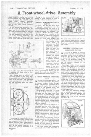
SUSPENSION. steering and driving arrangentents for front wheels are shown in patent No. 631,905, which comes from Duncan Industries (Engineers),* Ltd. and W. Renwick, Hall, of Park all, North Walsham, Norfolk.
In this scheme; the suspension consists of •a pair of swinging ,links, the upper one (I). of which •pivots about pin 2 and a universal joint (a) attached to a bracket (4) on-the hub assembly. This link appears at first sight to be part of the steering .mechanism, but this is not the case. The lower link (5) pivots about centre 6 at one end, and
at the other forms the outer socket of a ball-joint (7) fitted with a dustexcluding boot.
The driving axle is splined and universally jointed in the usual way, the outermost joint being located at the centre of the ball-joint, The axis about which steering occurs is the line joining the ball-joint with the upper universal joint.
The spring (8) is unorthodox; it consists of numerous rubber collars which are compressed under load between a bottom stop-face and a sliding bush (9) attached to the frame. This forms no part of the patent, however, as a helical steel spring is mentioned as an alternative.
A34 Owing to the comparatively small number of parts required, a claim is made for reduced production costs.
LIMITING TORQUE-CONVERTER OUTPUT
PATENT No. 631,607 deals with hydraulic transmissions of the torque-converter type, and refers to a means for lowering the output torque if the gear be loaded to a standstill. The patentee is L Becker, Toronto, Canada.
The drawing shows a section of the device which is constructed generally on well-known lines. An engine-driven impeller (I) is the input member. and the driven member (2) is carried on the output shaft. In operation, the fluid describes a circular path round the halfrings (3) and this flow normally takes place quite close to the half-rings. If, however, the output member be loaded enough to bring it to a standstill, the fluid path increases its diameter to the maximum possible. The essence of the patent is the provision of an obstructor (4) which. in the above circumstances, breaks up the smooth flow and thus diminishes the developed torque to a safe value.
A THREE-WHEELED DELIVERY
VAN
ATRADESMAN'S light delivery van is shown in patent No. 631.638, by H. Stieger,. Langtree Lodge, Brough, Yorks. The machine is powered by a small petrol engine, but driving is reduced to the simplest terms, one hand-lever being the sole control.
The drawing is a rear-end view, with parts of the body cut away to expose the engine and the single front wheel (I). Steering is performed by a tiller (2) extending over the top of the body, and the driver stands on the rear platform (3). Only one rear wheel is driven, the near-side one being chosen because is 'gives a better get-away when steering out from the kerb.
The engine drives the wheel via a two-speed gear, the ratios being automatically chosen by two Centrifugal clutches that come into action at different speeds, one being able 10 overrun the other .by means of a free-wheel. The engine is governed for speed. and the governor setting can be varied by either of the levers 4. .
These levers also apply the. brakes if moved away from the speed-increasing. direction. The brakes are also coupled to the platformon which the driver stands, so that braking is automatic should he leave the machine.
The whole engine and transmission unit is made to be readily detachable, so that spare units can be held for servicing a fleet of such vehicles. Several other patents refer to the same machine. They are numbered 594,628: 594.630 and 631,639.
ELECTRIC CONTROL FOR AUTOMATIC CLUTCH
ACLUTCH in which an electromagnet is used in conjunction with centrifugal weights forms the subject of patent No.. 631,783, which comes from L. Come, 56, Avenue Victor Hugo, Paris. In the proposed scheme, the centrifugal action is automatic, but it can be instantly released by the magnetic control.
Centrifugal weights (1) are mounted on a free sleeve which is not connected either to the flywheel or the output member. But normally it is driven in unison with the flywheel by means of a small friction clutch ring (2) which is loaded by spring bolts (3) on to the bellhousing (4) carried by the flywheel.
At speed, the action is automatic; the weights in moving outwards,. climb the curved face 5, and in doing so apply force to the main clutch elements (6).
If it be desired to free the clutch at high speed, an electric circuit energizes a pot-magnet (7) which then attracts the small clutch-plate and pulls it into braking contact with a friction-ring (8) on the magnet face.
This slows the centrifugal member and so unlocks the main drive. The speed of the centrifugal member can differ from that of the flywheel assembly, by virtue of an interposed ball-thrust (9).