


Foolproof
Page 51
If you've noticed an error in this article please click here to report it so we can fix it.
Wheel Aligner A CHECK of front-wheel toe
or toe-out in less than two minutes is passible with a new alignment gauge recently patented by the Elms Garage, Rednall Road, Birmingham, 31. Of particular importance is the tact that the accuracy of the reading is not affected by wheel buckle or tyre run out. The instrument is simple in operation, has no frail parts which can be easily damaged and it weighs less than 20 lb.
It can be left in place when adjustments are made, and the alteration in alignment may be read on a scale without re-setting any part of the tool The nature of the surface on which the vehicle is standing has no influence on the accuracy of the check unless the King pins or steering joints be badly worn and the ground is sloping laterally.
Simple Construction
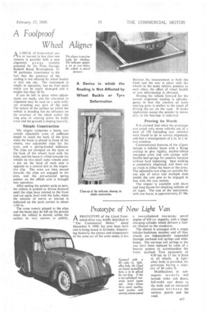
The aligner comprises a beam, two outside adjustable arms of sufficient length to reach the back of the tyres when the beam is placed in front of the wheels, two adjustable clips for the tyres, and a spring-loaded indicator. The clips are clamped on the tyres at the back of the wheels level with the ON, and the beam is rolled towards the vehicle on two small outer wheels until.
,pin on the head of each arm is opposite to a central, slot in the respective clip. The arms are then moved inwards, the clips are engaged in the slots, and the pin-actuated spring pointer OR the offside arm is brought into operation.
After setting the pointer scale to zero, the vehicle is pushed or driven forward until the clips have rotated to the front and are again level with the hubs, whenthe amount of toe-in or inc-out is indicated on the scale correct to about 1/64 in.
The arms remain pinned to the clips and the beam may be left on the ground when the vehicle is moved, unless the surface be very uneven or pebbly.
• Because the measurement at both the front and the rear is taken with the wheels in the same relative position to each other, the effect. of wheel buckle or tyre deformation _is obviated.
Moving the vehicle forward for the second alignment reading is advantageous in that the reaelion of worn steering parts is similar to the result of driving the car on the road. If brake application causes the painter to move, play in the bearings is indicated.
Proving its Worth It is claimed that whenthe prototype was tested only. seven vehicles out of a total of 170 (including new vehicles) were found to be in correct alignment, and that a misalignment of in, to 7 in.
was common. •
Constructional features of the aligner include a tubular beam with a flange overlap to give rigidity, double-ribbed one-piece arms andarm clamps with double leaf-springs for positive location without hard tightening. Spot welding is extensively employed, and there are no rivets in either the beam or the arms. The adjustable tyre clips are suitable for any size of cover and multiple slots enable the arm pins to be engaged in line with the tyre centres.
The aligner is available with short and long beams for checking vehicles of all types. The cost of the instrument, with one beam, is approximately £.7 10s.