


A Tail-gate Loader
Page 58
If you've noticed an error in this article please click here to report it so we can fix it.
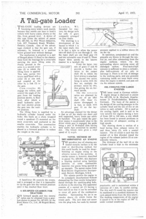
TAIL-GATE loading devices are I becoming more widely used, mainly because they enable one man to load a vehicle•with heavy crates, drums or the like, from ground level. ' A device of this type forms the Subject of patent No. 687,302, by Phil Wood-Irtdustries, Ltd., 857 Tecumseh Road, Windsor, Ontario; Canada. One of the advantages claimed is that the gate can, if necessary, be lowered to a position below ground level without damage.
The mechanism is attached to a pair of flanged plates (1) fixed to the chassis; these form the bearings for a cross-tube carrying the main lifting arms (2). freely pivoted in the arms is a second crosstube (3) to which the lifting force is applied. This tube carries two levers each‘fitted with a roller (4) at one end, and coupled at the other by a link (5) to the gate.
Cam-tracks (6) engage the rollers, and
control the angle of the 3gate from the loading position shown, to floor level, after which a small hydraulic cylinder (not shown) pivots the gate into the vertical position.
The lifting force is supplied by a hydraulic cylinder located under the body; this hauls on a chain wrapped round a quadrant (7) mounted on the main cross-tube and anchored to the smaller cross-tube. This construction enables the hydraulic cylinder to be placed in a forward position to reduce the weight at the rear.
A hand-lever (8) controls the events, and is arranged so that it is impossible to tip the gate into the vertical position until it has reached floor level.
A SIX-SPEED GEARBOX FOR TRACTORS
SIX forward speeds and two reverse ratios can be obtained from a gearbox shown in patent No. 687,052, by the Ford Motor Co., Ltd., 88 Regent Street,
A40
London, W.I. Intended for tractors, the design calls for only 11 gears compactly arranged on four shafts.
The drawing is-a development of the. layout in 'which 1 is the input shaft; this is in fact 'a tube to allow the power take-off shaft (2) to run through it. On the input shaft are one fixed gear (3) and two selectable ones (4 and 5). These impart three speeds in the known manner to a layshaft (6).
From the latter, two sets of gears (7 and 8) provide a further two ratios to the output shaft (9) to which the bevel pinion is attached. The second two ratios, being in series with the first set, multiply the primary ratios by two, thus giving the six forward speeds.
The two reverse ratios are obtained by the use of an idler shaft (10). Gear 11, shown disengaged, is, in fact. in mesh with gear 12 on the layshaft.
An advantage claimed for the design is that as all the shafts are short and well supported, heavy loads can safely be-handled. The gate round the gearlever makes it exceptionally clear to the driver which gear is engaged, the guide being a pair of H-shaped slots having their centre bars connected by another slot. The lowest ratio gives a road speed of 11 m.p.h.
NOVEL METHOD OF DECARBONIZING AN ENGINE
THE speediest way of cleaning any fouled metallic surface is by the sand or shot-blasting method, but this could hardly be used for decarbonizing an engine owing to the abrasive nature of the particles. A similar system is, however, described in patent No. 684,905; this discloses a blasting method using harmless particles of some combustible material, rice grains being quoted as an example. The patent comes from Kent-Moore Organization Incorporated, Detroit, Michigan, U.S.A..
The scheme permits the engine to be compl.e.tely decarbonized without dismantling, the blast nozzle being introduced through the sparking-plug hole, as shown in the drawing. The apparatus consists of a central jet (I) having a bent end (2) so that it can be swivelled to cover all parts of the combustion chamber. Surrounding the jet is an annular sleeve (3) which forms the return path. The unit does not screw into the plug hole, but seals by manual pressure applied to a rubber sleeve (4) on the tip.
In operation, compressed air and the granules arc blown in through the central jet, and after rebounding from the engine surfaces, return via the surrounding sleeve carrying away all dislodged carbon. Four-and-a-hP,If minutes is sufficient to clean a cylinda, plus half-a-minute of air only to scavenge it. There is no risk of damage to the working parts, and any granules remaining inside are soon burnt away when the engine is started, and pass out via the exhaust system.
OIL COOLING FOR LARGE ENGINES
THE latest trend in German vehicle/ engine design is disclosed in patent No. 687,528, by K. Maybach, Zepplinstrasse 21 Friedrichshafen, Bodensee, Germany. The basis of the patent is the design of the cooling passages in the cylinder head and the use of five or six valves to each cylinder. Oil is used as the cooling liquid, and is said to be very suitable for engines having a bore of from 140 to 160 mm., a size which has been found to present problems in the provision of adequate cooling at
high speeds. • The drawing shows a section of a head having three exhaust valves (1) and three inlets (2), with a central injector. The oil circuit is such that the cooled oil is first directed round the region of the exhaust jackets (3) at considerable velocity.
The thickness of the wall (4) at the cylinder head is kept to the minimum practicable, and is maintained within a tolerance of I mm. by careful casting. The thin wall (5) round the injector can be machined to a standard thickness by tools passed down from the bore above. The working temperature of the engine IS stated to be in the region of 140° C. under normal conditions.