


A NEW WESTINGHOUSE BRAKE ARRANGEMENT.
Page 70
If you've noticed an error in this article please click here to report it so we can fix it.
A Résumé of Recently Published Patent Specifications.
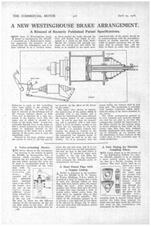
THE form of Westinghouse brake shown in specification No. • 273,237 is described as a fluid-pressure brake, but apparently the pressure is obtained frOm the atmosphere, and it is later referred to as a vacuum brake.
Reference is made to the controlling valve used, which is the subject of patent• No. 246,791. A valve of —this type is situated at the left-hand end of the vacuum cylinder shown in both views and is operated by a link connected to the floating lever (E), the upper end of which is pivoted to a crank on the brake shaft. A link connects-this floating lever to the pedal, so that a certain proportion of the driver's power is employed directly in the application of the brake and a smaller amount of the power goes to open the controlling valve.
Vacuum in the large cylinder causes the piston to move to the left and by
so doing applies the brake through the lever and slotted link which is connectedto a crank on the brills.: shaft. Should the vacuum fail through any cause the slotted link will allow the brake to be applied in the usual man
ner entirely by the effort of the driver on his pedal.
The upper view shows, in section, the construction of the piston, which is provided with a cup leather and •a means for lubricating the same through • the central hollow of the connecting rod. It will be seen that the connecting rod is provided with a ball joint where it joins its piston, sosthat it can follow the arc described by the lever to which it is attached without die-. turbing the • piston in relation to the cylinder. The lubricator at the end of the connecting rod supplies grease to the ball joint as well as to the cup leather. As it is necessary that the' right-hand side of the piston should be in communication with the atmosphere, bellows of flexible material are provided to permit movement but at the same time to exclude dust. An air filter is fitted in order that what air comes within the bellows shall be free from grit. The mechanism is provided with another lubricator which facilitates the oiling of the sleeve attached to the piston..
' The whole arrangement appears to be very complete and carefully thought out, and We are glad to see that this company has realized the importance of the effort exerted by the vacuum being in direct relation to that made by the driver, also that they have replaced flexible diaphragms with pistons working in cylinders, as . we pointed out the importance of these features in the earlier days of this particifiar type of brake mechanism. •
A Valve-actuating Device.
THE device shown in the aceempany ing drawing is the subject of patent No. 276,669, by Motosacoehe. S.A., of Geneva; which provides a means whereby the arc described by the rocking arm which operates the valve can be made to accommodate itself to the straight-line movement of the valve stem with the minimum of frictiOn and wear. The rounded end of the adjusting screw impinges upon It cap which fits loosely over the end of the valve stem, sufficient play being allowed between the bore of the cap and the stem to allow for the different natures of the movements, as the cap can slide about an the stem. No provision is mentioned for lubrication be 60, tween the cap and stem, and it is not easy to see how even an oily atmosphere can find its way to the part where it is required. If turned-up edges were provided on the cap and holes for lubrication to find its way downward were arranged, the difficulty might be satisfactorily overcome.
A Steel Petrol Pipe with a Copper Lining.
A TUBE is described in the specifica tion No. 279,050 of H. W. Bundy, of Wayne, Michigan, 'U.S.A., which is formed of a strip of copper and a strip of steel run through rollers so that they both form butted tubes, the copper within the steel. After leaving the machine that draws them Into the form of tubes they pass through a bath, of melted solder, which unites them, the butts being on opposite sides so that leakage shall not be possible. The• object of the invention appears to be to provide a tube that will.be less likely to be affected by fatigue due to vibration, but mild steel will fracture almost as easily as copper.
A New Fixing for Flexible Coupling Discs.
THE object aimed at in the patent of
the Self-Scaling Rubber Co., Ltd., Na. 285,167, appears to be to provide a more lasting means for securing the disc of a flexible coupling to its spiders. The steel plates used as reinforce men ts f or the holes Through which the bolts pass are pressed into the shape shown, where a boss is formed which
extends, halfway through the hole in the disc and is met by the plate on the 'opposite side. Dy this means a complete bush is formed which should prevent the bolts from wearing the holes oval and thus avoid the vibration and wear in the transmission line consequent on this factor.