 1
1 2
2 3
3 4
4 5
5 6
6 7
7 8
8 9
9 10
10 11
11 12
12 13
13 14
14 15
15 16
16 17
17 18
18 19
19 20
20 21
21 22
22 23
23 24
24 25
25 26
26 27
27 28
28 29
29 30
30 31
31 32
32 33
33 34
34 35
35 36
36 37
37 38
38 39
39 40
40 41
41 42
42 43
43 44
44 45
45 46
46 47
47 48
48 49
49 50
50 51
51 52
52 53
53 54
54 55
55 56
56 57
57 58
58 59
59 60
60 61
61 62
62 63
63 64
64 65
65 66
66 67
67 68
68 69
69 70
70 71
71 72
72 73
73 74
74 75
75 76
76 77
77 78
78 79
79 80
80 81
81 82
82 83
83 84
84 85
85 86
86 87
87 88
88 89
89 90
90 91
91 92
92 93
93 94
94 95
95 96
96 97
97 98
98 99
99 100
100 101
101 102
102 103
103 104
104 105
105 106
106 107
107 108
108 109
109 110
110 111
111 112
112 113
113 114
114 115
115 116
116 117
117 118
118 119
119 120
120 121
121 122
122 123
123 124
124 125
125 126
126 127
127 128
128 129
129 130
130 131
131 132
132 133
133 134
134 135
135 136
136 137
137 138
138 139
139 140
140 141
141 142
142 143
143 144
144 145
145 146
146 147
147 148
148 149
149 150
150 151
151 152
152 153
153 154
154 155
155 156
156 157
157 158
158 159
159 160
160 161
161 162
162 163
163 164
164 165
165 166
166 167
167 168
168 169
169 170
170 171
171 172
172 173
173 174
174 175
175 176
176 177
177 178
178 179
179 180
180 181
181 182
182 183
183 184
184 185
185 186
186 187
187 188
188 189
189 190
190 191
191 192
192 193
193 194
194 195
195 196
196 197
197 198
198 199
199 200
200 201
201 202
202 203
203 204
204 205
205 206
206 207
207 208
208 209
209 210
210 211
211 212
212 213
213 214
214 215
215 216
216 217
217 218
218 219
219 220
220 221
221 222
222 223
223 224
224 225
225 226
226 227
227 228
228 Compression Injection
Page 176
If you've noticed an error in this article please click here to report it so we can fix it.
AN injection pump operated by cylinder compression is described in patent No. 841,202. Injection timing is controlled electrically. (P. Bessiere, 15 rue Freycinet, Paris.)
Referring to the drawing, the cylinderhead contains a sliding piston (1) which, on its upstroke, pumps fuel in the space 2, down through the central bore and out of the spray nozzle (3). On the upstroke, fresh fuel is drawn in through the inlet port (4).
Regulation is given by varying the height of an adjustable abutment (5). This carries a pinion (6) which meshes with a conventional rack-rod.
The timing of the charge is controlled by an elect ro-magnet (7). When this is energized, the air piston is prevented from rising because push-rods (8) abut against the .underside of the magnet top-plate (9). When current to the magnet is interrupted, the top plate is free to rise and injection can take place.
The magnet circuit can be interrupted by a switch responsive to cylinder pressure, or by one worked by the camshaft. By controlling the current with a rheostat, slight timing variations can be obtained because a strongly excited magnet takes longer to release its energy than a weaker sine, V ARIA BLE,-RATIO STEERING
LTHOUGH power-assisted steering 1-k mechanism for heavy vehicles permits lower steering ratios, these can make the steering unduly sensitive in the mid-position. A steering mechanism that provides a higher gear in the midposition compared with that at full lock is shown in patent No. 839,954. (General Motors Corp., Detroit, Michigan, U.S.A.).
The drawing shows a powered steering box according to the invention. The column turns in a ball-bearing thread (1)
formed in a combined nut .and piston (2). Hydraulic pressure, controlled by a column-operated valve (not shown), thrusts the piston one way or the other, turning the rocker-shaft (3).
The piston has normal rack teeth cut on a concave pitch line but the sector has unusual teeth, the middle one (4) being longer than those at the side. This gives a decreasing mechanical advantage on each side of the centre position. Thus, in the central position the sector acts as a large gear but reduces its effective pitch diameter as the shaft turns.
ELEVATING BODY
/X BODY that can be lowered to Pl. ground level is shown in patent No. 840,254. (Wumag Niederrhein Waggonmid Maschienenbau G.m.b.H., 60 Hentrichstrasse, Krefeld Rheinhafen, Germany.)
The drawing shows the body at the normal travelling height. It is normally locked in this position, but can be lowered by a pair of links (1 and 2) pivoted on a cross-member (3). The chassis frame is U-shaped in plan, and the wheels are independently suspended to avoid an obstruction between the side members. Front-wheel drive is employed.
A hydraulic ram (4) provides lifting power and lowering control. The patent covers also the use of variable-length parallel links so that the body can also be tipped.
CONTROLLED BRAKING
ADEVICE that cuts out braking action if retardation exceeds a set degree is shown in patent No. 842,239. Once the deceleration rate has fallen, full braking action is restored automatically. (Recherches Etudes Production R.E.P., 38 Avenue Pierre ler de Serbie, Paris 8e.)
The unit shown in the drawing may be attached to, or driven by, one of the road wheels. It consists of a casing (1) and an inertia flywheel (2) freely journalled in it. The flywheel is coupled to the easing by a clock-type spring (3) which causes it to revolve with the casing.
With excessive deceleration, however, the flywheel overcomes the spring and by rotating relative to the casing, makes an electric contact. This consists of a spring blade (4) which lies in a clearance hole, but touches the side if the flywheel turns. The electric circuit operates a magnetic valve in the
hydraulic system and prevents further braking until the contacts are re-opened.
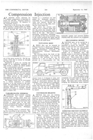
SELF-LOADING DEVICE
I-1 A LIFTING gear, to be carried by a vehicle to assist in loading, is described in patent No. 840,418. The hoist can luff and slew and takes up little space when not in use. (Hydrauliska Industri A.B., Hudiksvall, Sweden.)
A pillar (1) behind the cab is also the cylinder of a hydraulic ram. The slewing motion is provided by hydraulic cylinders (2) with rack teeth on their piston rods. These mesh with a pinion (not shown) on a collar (3) and so impart the turning movement to the pillar.
The main hydraulic ram is shown at 4; this carries a pivot (5) for the jib (6) which is pivoted at its other end on a link (7). The boom itself can be folded away. It is jointed at a .mid-point
(8) and when a ram (9) is energized, swings completely over and comes to rest on the top of the surface (10), to reduce its length. The main ram is then retracted, bringing the doubled-up boom inboard.
IMPROVED FRICTION MATERIAL
FROM General Motors Corp., Detroit, Michigan, U.S.A., comes patent No. 841,817. This deals with a brake mechanism with two shoes made from different material. One is non-metallic, but the other is made of sintered ferrous metal, preferably with graphite added. The metallic material withstands high temperature, whilst the other is better at low ,ternPeratures and tends to prevent squeal.