 1
1 2
2 3
3 4
4 5
5 6
6 7
7 8
8 9
9 10
10 11
11 12
12 13
13 14
14 15
15 16
16 17
17 18
18 19
19 20
20 21
21 22
22 23
23 24
24 25
25 26
26 27
27 28
28 29
29 30
30 31
31 32
32 33
33 34
34 35
35 36
36 37
37 38
38 39
39 40
40 41
41 42
42 43
43 44
44 45
45 46
46 47
47 48
48 49
49 50
50 51
51 52
52 53
53 54
54 55
55 56
56 57
57 58
58 59
59 60
60 61
61 62
62 63
63 64
64 65
65 66
66 67
67 68
68 69
69 70
70 71
71 72
72 73
73 74
74 75
75 76
76 77
77 78
78 79
79 80
80 81
81 82
82 83
83 84
84 85
85 86
86 87
87 88
88 89
89 90
90 91
91 92
92 93
93 94
94 95
95 96
96 97
97 98
98 99
99 100
100 101
101 102
102 103
103 104
104 105
105 106
106 107
107 108
108 109
109 110
110 111
111 112
112 113
113 114
114 115
115 116
116 117
117 118
118 119
119 120
120 121
121 122
122 123
123 124
124 125
125 126
126 127
127 128
128 129
129 130
130 131
131 132
132 133
133 134
134 135
135 136
136 137
137 138
138 139
139 140
140 141
141 142
142 143
143 144
144 145
145 146
146 147
147 148
148 149
149 150
150 151
151 152
152 153
153 154
154 155
155 156
156 157
157 158
158 159
159 160
160 161
161 162
162 163
163 164
164 165
165 166
166 167
167 168
168 169
169 170
170 171
171 172
172 173
173 174
174 175
175 176
176 177
177 178
178 179
179 180
180 181
181 182
182 183
183 184
184 185
185 186
186 187
187 188
188 189
189 190
190 191
191 192
192 193
193 194
194 195
195 196
196 197
197 198
198 199
199 200
200 201
201 202
202 203
203 204
204 205
205 206
206 207
207 208
208 209
209 210
210 211
211 212
212 213
213 214
214 215
215 216
216 217
217 218
218 219
219 220
220 221
221 222
222 223
223 224
224 225
225 226
226 227
227 228
228 DAIMLEI ;ACE ABOUT
Page 114
Page 115
Page 116
If you've noticed an error in this article please click here to report it so we can fix it.
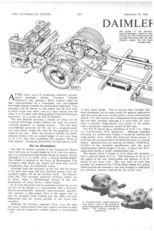
AFTER many years of producing relatively conventional passenger chassis, Transport Vehicles (Daimler), Ltd., sprung a Show surprise today by their announcement of a completely new rear-engined low-height chassis suitable for double-deck bodywork. Two examples will be shown to the public for the first time at Earls Court next week—one as a bare chassis and the other as a 77-seater with Metropolitan-Cammell-Weymann bodywork. It is called the R.E.30 Fleetline.
The new Daimler provides a chassis on which can be mounted low-bridge bodies without the need for uncon ventional gangway or seating layouts. This has been accomplished primarily by the use of a dropped-centre rear axle which avoids the need for the gangways to be raised at the rear. Thus, the chassis is suitable for frontentrance bodies with an overall height of not more than 13 ft. 4 in., but with completely flat gangway floors in both saloons. Maximum permissible seating capacity is 78.
Bus I or Birmingham
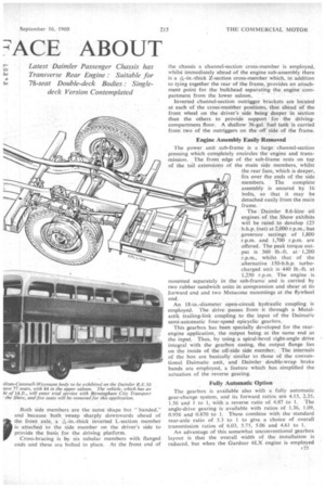
The M.C.W.-bodied example at the Commercial Motor Show will have an overall height of 14 ft., but it is equivalent to a conventional high-bridge design in interior layout, although it is 6 in. lower than a normal double-decker. The exhibit is finished in the livery of Birmingham City Transport, with whom the vehicle will enter trial service immediately after the Exhibition closes.
Although both the examples of the new R.E.30 chassis to be seen next week will have Daimler power units, the standard engine will be the Gardner 6LX. The Daimler CD.6 Mk. VIII normally aspirated 125-b.h.p. engine can be fitted, whilst a turbocharged version of this unit developing 150 b.h.p. forms a third choice.
In all cases the power unit is mounted transversely across the rear of the chassis as a sub-assembly with a Daimatic electric-pneumatically operated semi-automatic gearbox. This includes a right-angled drive at the engine end, so that the propeller shaft leading into the offset rear-axle differential unit lies almost parallel to the frame side members.
Although the Daimler engineers have, over the past few years, experimented with such relative novelties as disc brakes and air suspension, neither feature is incorporated E24 in their latest design. This is because they consider that such techniques are not quite ready for general application and that most operators would prefer a more conventional chassis. For this reason also, independent front suspension has not been adopted, although it is more than six years since a Daimler single-decker was shown to the public with a prototype suspension system of this type.
The R.E.30 chassis has a wheelbase of 16 ft. 3 in., which can accommodate 30-ft. bodywork. Although intended primarily for double-deck bodies it would be suitable for single-decker work, whilst the front-end frame layout is such that the accommodation of left-hand drive is a simple matter. Identical tyres are used on all wheels-10.00-20-in. (12-ply) in the standard speeification—and the gross recommended vehicle weight is 14 tons. A chassis for 36-ft. single-deck bodies is under consideration also.
The chassis frame is based on *--in.-thick side members with a general depth of 8 in. This increases to 9+ in. in the region of the rear wheel-arches and reduces to 5+ in. ahead of the front axle. The rear ends of each side member are reinforced by 7132-in.-thick bolted box plates, which provide the necessary rear-end strength to withstand the cantilever stresses imposed by the power unit.
Both side members are the same shape but "handed," and because both sweep sharply downwards ahead of
it the front axle, a i-in.-thiek inverted L-section• member is attached to the side member on the driver's side to provide the basis for the driving platform.
Cross-bracing is by six tubular members with flanged ends and these are bolted in place. At the front end of
the chassis a channel-section cross-member is employed, whilst immediately ahead of the engine sub-assembly there is a 13;s-in.-thick Z-section cross-member which, in addition to tying together the rear of the frame, provides an attachment point for the bulkhead separating the engine compartment from the lower saloon.
Inverted channel-section outrigger brackets are located at each of the cross-member positions, that ahead of the front wheel on the driver's side being deeper in section than the others to provide support for the drivingcompartment floor. A shallow 36-gal. fuel tank is carried from' two of the outriggers on the off side of the frame,
Engine Assembly Easily Removed The power unit sub-frame is a large channel-section pressing which completely encircles the engine and transmission. The front edge of the sub-frame rests on top of the tail extensions of the main side members, whilst the rear face, which is deeper, fits over the ends of the side members. The complete assembly is secured by 16 bolts, so that it may be detached easily from the main frame.
The Daimler 8.6-litre oil engines of the Show exhibits will be rated to develop 125 b.h.p. (net) at 2,000 r.p.m., but governor settings of 1,800 r.p.m. and 1,700 r.p.m. are offered. The peak torque output is 360 lb.-ft. at 1,200 r.p.m., whilst that of the alternative 150-b.h.p. turbocharged unit is 440 lb.-ft. at 1,250 r.p.m. The engine is mounted separately in the sub-frame and is carried by two rubber sandwich units in compression and shear at its forward end and two Metacone mountings at the flywheel end.
An 18-in.-diameter open-circuit hydraulic coupling is employed. The drive passes from it through a Metalastik trailing-link coupling to the input of the Daimatic semi-automatic four-speed epicyclic gearbox.
This gearbox has been specially developed for the rearengine application, the output being at the same end as the input. Thus, by using a spiral-bevel right-angle drive integral with the gearbox easing, the output flange lies on the inside of the off-side side member. The internals of the box are basically similar to those of the conventional Daimatic unit, and Daimler double-wrap brake bands are employed, a feature which has simplified the actuation of the reverse gearing.
Fully Automatic Option The gearbox is available also with a fully automatic gear-change system, and its forward ratios are 4.15, 2.35, 1.56 and 1 to 1, with a reverse ratio of 4.87 to 1. The angle-drive gearing is available with ratios of 1.36, 1.09, 0.956 and 0.870 to 1. These combine with the standard rear-axle ratio of 5.3 to 1 to give a choice of overall transmission ratios of 6.03, 5.75, 5.06 and 4.61 to 1.
An advantage of this somewhat unconventional gearbox layout is that the overall width of the. installation is reduced, but when the Gardner 6LX engine is employed 25 a modified layout has to be adopted, .becaUse• it is longer than the Daimler 8.6-litre unit. .In the Gardner installation, the output section of the box lies below the level of the mainshaft, thereby permitting the main section to be nearer the engine flywheel. This arrangement saves the 9 in. necessary to accommodate the Gardner engine.
A rubber four-point mounting carries the complete gearbox assembly, and the castaluminium radiator is flexibly mounted above the gearbox casting.
The cooling system is pressurized to 4 p.s.i. and a 22-in.diameter eight-bladed fan is carried in a casting mounted on the radiator, block. This incorporates a close-fitting cowl. A jackshaft is .driven from the rear of the engine -camshaft and drives the fan through a triple V-belt at 1.4 •times engine speed. The air-intake duct to the
oil-bath air cleaner lies adjacent to the radiator block and ensures an .intake of cold' air to increase engine efficiency.'
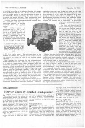
• Steel castings are employed for the dropped-centre double-reduction rear axle. The drive from the gearbox is by way of a short Hardy Spicer propeller shaft and passes into spiral-bevel gearing on the right of the axle assembly. From the differential the drive passes through a pair of straight spur .gears, the right-hand gearing being integral with the differential assembly, whilst the left hand gearing is driven through a short shaft. This gearing raises the drive to above the level of the springs and the design of the axle is such that most of the com ponents at each side of the assembly are interchangeable, including the secondary drive shafts to the hubs.
Constant-rate 62-in.-long underslung semi-elliptic springs are employed at the rear axle, and are controlled by Armstrong double-acting telescopic dampers. Internal expanding strut-type cam brakes are used at the rear axle and incorporate Daimler automatic adjusters. The drum diameter is 16 in., whilst the linings are 8 in. wide, giving an effective frictional area of 460 sq. in. BendixWestinghouse diaphragm actuators are employed, whilst the single-pull hand-brake lever operates the brakes through rod linkages and a cross-shaft. A dual-circuit air-pressure system can be supplied to order.
The front axle beam is an Hsection steel stamping, and Glacier DU p.t.f.e.-lead bearing material is used to support the stub axles and to take the thrust of the chromium-plated king-pins. Dualrate front springs with an effective length of 50 in. are employed, and the leaves,: like those of the rear springs, are 4 in. wide. Armstrong DAS.12 lever-type dampers • ' are fitted. The front brakes measure 16 in. by 4.75 in., with a total lining area of 273 sq. in. and, as with the rear units, they are diaphragm operated through automatic adjusters. The brakes are controlled by a single E valve actuated by a conventional pedal.
Mantes cam-and-double-roller steering gear has been adopted, and the steering box is bolted to the foremost chassis-frame cross-member, through which the two-piece drag link passes. This drag link is divided at a relay lever mounted ahead of the front axle.
A 2 I -in.-diameter steering wheel is fitted. and the -steer Mgbox ratio is 28.5 to 1, giving 51 turns of the wheel from lock to lock. The turning circle measured at the wheels is just under 60 ft., whilst the swept circle is 63 ft.
A Lockheed hydraulic system links the treadle-type accelerator pedal with the engine injection pump. The Lockheed master cylinder, as with the brake pedal, is mounted on the foremost cross-member, whilst the brake valve is placed on one of the cab-floor cross-bearers.
The C.A.V. 24v. electrical system is supplied by a diameter C.A.V. alternator, feeding the 130-amp.-hr. batteries through a rectifier. Chassis equipment inciudcs a bulkhead forward of the engine compartment and plastics engine-compartment covers.