


Progress in Petrol Injection for Vehicle Engines
Page 33
If you've noticed an error in this article please click here to report it so we can fix it.
Scintilla, Ltd., Introduces Equipment for Converting a Standard Petrol Engine to Operate on the Induction-pipe Injection System Instead of Drawing Fuel from a Carburetter
roR aircraft powered by petrol engines, one advantage 1of injecting fuel instead of supplying it through a carburetter is *ell known. For road vehicles, however, the attraction of the scheme is less obvious.
Centrifugal force and changes in the direction of the gravitational force on the fuel in the carburetter must theoretically have some influence on the functioning of the instrument, but in practice this seems to be negligible. Also, it is generally admitted that it is practically impossible to make a carburetter which delivers an absolutely correct mixture under all conditions of running, but here again there is little fault to be found with the standard instruments with which we are familiar.
However, it .cannot be without purpose that Scintilla, Ltd., has devised apparatus for converting an ordinary four-cylindered vehicle engine to run with petrol injection to the induction pipe instead of with a carburetter.
No doubt the company sees possibilities for the scheme, perhaps in connection with better atomization and improved volumetric efficiency, and certainly the interest attached to it is considerable. The invention emanates from the Swiss Scintilla concern and it is detailed in recently published British Patent Specification No. 547,137.
The device incorporates an injection pump—based on the design commonly used for compression-ignition engines— which is driven by chain or belt from the crankshaft. Control of the pump is by a diaphragm forming the wall of a vacuum chamber connected by a tube with the induction pipe. Thus, the quantity of fuel delivered is obviously a function of engine speed and manifold suction. Accordingly the mixture should always be correct.
It will be appreciated that, in the oil engine, power output is regulated by quality control, that is by varying the proportion of oil fuel to air. On the other hand, the petrol-engine output is governed by quantify control, that. is by varying the amount of mixture (of a constant fuelair proportion) that is admitted to the cylinders.
Largely because of the high compression and temperature obtaining in the oil-engine combustion chamber during the period of injection, the fuel will burn, however small the quantity, but in order that the mixture in a petrol-engine cylinder, at relatively low pressure and temperature. may be sufficiently inflammable, its proportions must be within rigidly fixed and fairly close limits.
From this, the foregoing point about controlling the mixture by combined engine speed and throttle opening will be appreciated in its proper significance. It may be that the advantages of the system turn upon this matter.
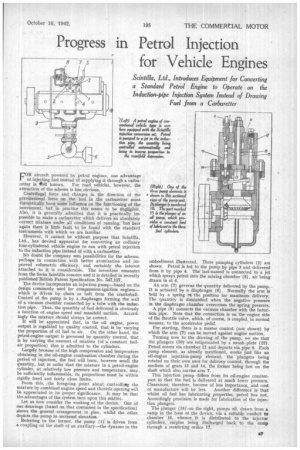
Let us now consider the working of the device. One of our drawings (based on that contained in the specification) shows the general arrangement in plan, whilst the other depicts the pump in sectional elevation.
Referring to the former, the pump ( is driven from a coupling on the shaft of an auxiliary—the dynamo in the embodiment illustrated. Three pumping cylinders (2) are shown. Petrol is fed to the pump by pipe 3 and delivered from it by pipe 4. The last-named is connected to a jet which sprays petrol into the mixing chamber (5), air being drawn in at 6.
An arm (7) governs the quantity delivered by the pump. It is actuated by a diaphragm (8). Normally the arm is held by a spring in the position for maximum delivery. The quantity is diminished when the negative pressure in the diaphragm chamber overcomes the spring pressure.
A pipe (9) connects the vacuum chamber with the induction pipe. Note that the connection is on the engine side of the throttle valve, which, of course, is coupled, in normal manner, to the accelerator pedal.
For starting, there is a master control (not shown) by which the arm (7) can be moved against engine suction_
Turning now to the drawing of the pump, we see that the plungers (10) are reciprocated by a swash plate (12). Petrol enters via chamber 11 and departs via pipe 4, Each , pump element, as already mentioned, works just like an oil-engine injection-pump element, the plungers being rotated on their own axes for delivery control, through the medium of gears 13 and 14, the former being fast on the shaft which also carries arm 7.
This injection pump differs from its oil-engine counterpart in that the fuel is delivered at much lower pressure. Clearances, therefore, become of leas importance, and cost of manufacture will be less. Another difference is that whilst oil fuel has lubricating properties, petrol has not. Accordingly provision is made for lubrication of the injection plungers.
The plunger (15)` on the right, pumps oil, drawn from a sump in the base of the device, via a suitable conduit to chamber 16, whence, it is distributed to the injector cylinders, surplus being disCharged back to the sump through a restricting orifice 17.