


An Oil En2ine Combustion System
Page 54
If you've noticed an error in this article please click here to report it so we can fix it.
A Résumé of Recently Published Patent Specifications
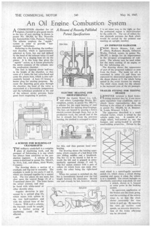
A COMBUSTION chamber for oil rt engines, claimed to give good results in the way of easy starting, is shown in patent No. 584,966, by Soc. Nouvelle des Automobiles Unic, Puteaux, France. The scheme employs the " squish " system in order to provide " lastmoment " turbulence.
Referring to the drawing, the combustion chamber, which is approximately spherical in form, has one end defined by the head of the exhaust valve (1) and the other by a sloping boss (2) on the piston. It is this boss that gives the "squish" action, as it forces practically the entire contents of the cylinder into the combustion chamber.
The fuel is injected about half-way in the height of the chamber, so that some of it meets the hot valve-head and some the piston boss, which is also substantially heated. A bore (3) houses a heater plug for starting purposes Because the departing gases pass through the chamber, the head of the valve is maintained at a favourable temperature and the turbulence produced at the end of the exhaust stroke prevents burnt gases from stagnating in pockets.
A SCHEME FOR BUILDING-UP CRANKSHAFTS
TIE ordinary crankshaft is a complex Piece of machining work, and the prospect of fabricating it is one which has always been attractive to the pro
duction engineer. A scheme of this nature is disclosed in patent No. 584,635, by Alvis, Ltd., and others, Alvis Works, Coventry. The drawing shows a section of a crankpin and big-end in assembly. The crankpin is made in two parts (1 and 2), which are clamped together by a central bolt. The two pieces do not meet, but abut upon the central flange (3) of a T-sectioned sleeve (4). The latter forms the actual journal, and may be faced with white-metal or other durable alloy.
Angular deviation is prevented by a splined plug (5), which mates with splines in the two half-members and with the splined bore of the T-sleeve. With such a scheme, the big-ends could be unsplit, and a further saving of machining could this be effected.
ELECTRIC HEATING FOR DROP-FORGINGS
FROM the Austin Motor Co., Ltd., and others, Longbridge Works, Birmingham, comes, in patent No. 584,771, a scheme for the rapid heating of steel bars intended for making drop-forgings. The bars are heated by passing a heavy electric current through them, but, as in production work, the cut-off end of the bar is already hot from the previous heating, the method is arranged to allow
for this, and thus prevent local overheating.
The drawing shows the heating apparatus, which consists of a bed fitted with two sliding saddles and a headstock. The bar (I) to be heated is fed in towards the left and is gripped in pneumatically operated clamps (2 and 3). The bar makes contact with a pair of rollers (4) which form one main electrode, the other being the right-hand clamp.
When the current is switched on, the bar is immediately heated over the full length between the electrodes. Should one end already be hot. however, clamp 2 is set some way to the right, so that the preheated region is short-circuited by the cable (5). The use of rollers for one electrode prevents the flash which would be caused by the pointed end meeting an upright member.
AN IMPROVED RADIATOR
L-110M Morris Motors, Ltd., and
others, Radiators Branch, Osberton Works, Oxford, comes, in patent No. 584,107, a design for an improvement in the air-space arrangements of radiators. The scheme may be used either for the main cooling of an engine or for the lubricating oil.
The drawing shows the appearance of part of the proposed radiator as seen from the front. The water (or oil) is contained in tubes (1) and these are separated by sheet-metal spacers bent to the shape shown at 2, the whole being united in the, usual manner by tinning. The chief claim made for the scheme is the increased area of the air passages.
TRAILER FITTING FOR TESTING BRAKES
HOWEVER accurate a fixed braketesting machine may be, it can never quite reproduce road conditions, and to obtain more representative data on braking is the object of a device shown in patent No. 584,840, by A. Brunner, St. Louis, Missouri, U.S.A.
The apparatus described is a small wheeled trailer, which is towed by the vehicle under test. It consists of a single wheel, ball-jointed to, say, the bumper, and spring-loaded to provide road-holding properties. Driven by the road wheel is a centrifugally operated switch (1), which closes a circuit during running and opens it when the vehicle is at a standstill. The circuit includes an electrically controlled stop-clock (2) and a switch, shown at 3, located at some point in the braking system. In operation, application of the brakes sets the clock going, and the' arresting of the vehicle stops it, so that the clock Shows accurately the time taken to pull up. By equating the time to various road speeds, an accurate determination of the brake efficiency can be obtained.