


Front Suspension for Three-wheelers
Page 54
If you've noticed an error in this article please click here to report it so we can fix it.
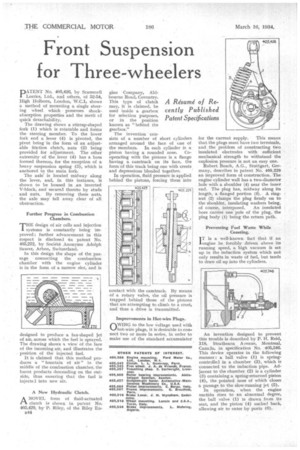
A Résumé of Recently Published Patent Specifications PATENT No. 405,426, by Scarnmell Lorries, Ltd., and others, of 52-54, High Holborn, London, 'W.C.1, shows a method of mounting a single steering wheel which possesses shockabsorption properties and the merit of quick detachability.
. The drawing shows a stirrup-shaped fork (I) which is rotatable and forms the steering member. To the lower fork end a lever (4) is pivoted, the pivot being in. the form of an adjustable friction clutch, nuts (2) being provided for adjustment. The other extremity of the lever (4) has a. boss formed thereon, for the reception of a heavy suspension spring (3), which is anchored to the main fork.
The axle' is located midway along the lever, and, in this instance, is shown to be housed in an inverted V-block, and secured thereto by studs and nuts. By removing these nuts, the axle may fall away clear of all obstruction.
Further Progress in Combustion Chambers.
THE design of air cells and injection systems is constantly being improved; further advancement in this respect is disclosed tin patent No. 405,272, by Societe Anonyme Adolph Saurer, Arbon, Switzerland.
In this design the shape of the passage_ connecting the combustion chamber with the engine cylinder is in the farm of a narrow slot, and is designed to produce a fan-shaped jet of air, across which the fuel is sprayed. The drawing shows a view of the face of the incoming air, and ilinstrates the position of the injected fuel.
It is claimed that this method produces a 'fountain of air" in the middle of the combustion chamber, the burnt products descending on the outside, thus ensuring that the fuel is injectel into new air.
A New Hydraulic Clutch.
ANOVEL form of fluid-actuated clutch is shown in patent No. 405,429, by P. Riley, of the Riley En544
gine Company, Aidbourne Road, Coventry. This type of clutch may, it is claimed, be used inside a gearbox for selection purposes, or in the position known as "behind the gearbox."
The invention consists of a number of short cylinders arranged around the face of one of the members. In each cylinder is a piston having a rounded nose. Cooperating with the pistons is a flange having a camtrack on its face, the form of this track being one with crests and depressions blended together.
In operation, fluid pressure is applied behind the pistons, forcing them into contact with the camtrack. By means of a rotary valve, the oil pressure is trapped behind those of the pistons that are attempting to climb to a crest,. and thus a drive is transmitted.
Improvements in Hot-wire Plugs.
OWING to the low voltage used with hot-wire plugs, it is desirable to connect two or more in series, in order to make use of the standard accumulator
for the current supply. This means that the plugs must have two terminals, and the problem of constructing two insulated electrodes with sufficient mechanical strength to withstand the explosion pressure is not an easy one.
Robert Bosch, A.G., Stuttgart, Germany, describes in patent No. 405,229 an improved form of construction. The engine cylinder wall has a two-diameter hole with a shoulder (4) near the inner end. The plug has, midway along its length, a Hanged portion (A). A ringnut (2) clamps the plug firmly on to the shoulder, insulating washers being, of course, interposed. An insulated bore carries one pole of the plug, the plug body (I) being the return path.
Preventing Fuel Waste While Coasting.
I T is a well-known fact that if an engine be forcibly driven above its running speed, a high vacuum is set up in the induction system which not only results in waste of fuel, but tends to draw oil up into the cylinders.
An invention designed to prevent this trouble is described by P. H. Reid, 118, Strathearn Avenue, Montreal, Canada, in specification No. 405,346. This device operates in the following manner : a ball valve (I) is springcontrolled in a chamber (2), which is connected to the induction pipe. Adjacent to the chamber (2) is a cylinder (3) containing a. spring-returned piston (4), the pointed nose of which closes a passage to the slow-running jet (5).
In operation, when the engine suctidn rises to an abnormal degree, the ball valve (I) is drawn from its seat, and the piston (4) sucked back, allowing air to enter by ports (6)•