


Controlling Fuel Injection
Page 64
If you've noticed an error in this article please click here to report it so we can fix it.
in heavy-oil engines ASIMPLE method of controlling the time and duration of the airless injection of fuel in Diesel engines is described in patent No. 348,097, by lingo Junkers, 21, KaiserplatZ, Dessau, Anhalt, Germany.
The pump used is of that class where only one valve is employed, that being at .the outlet pipe; the piston runcoverjog and covering the inlet passage and acting as a valve.
• As the piston descends, vacuum is set up in the chamber until the hole (4) is uncovered, then fuel fills the Space, but is not, on the return stroke of the piston, expelled through the non-return valve so long as the hole• is uncovered. • It will be seen that the piston has a part cut away and is provided with a lever which can cause it partly to rotate. By turning the piston so that the cut-away part comes .over the hole, the moment a which the delivery takes Place can be delayed, also the length of time of delivery can be regulated, as, by means of the cut-away part, the hole can be opened-as the piston travels upwards.
In this arrangement the stroke of the piston is constant, and all the regulation of time and duration of the injection can be controlled by turning the piston slightly around. This patent has become void.
A New Arrangement of Road Rollers.
IN patent specification No. 347,899,
W. T. Bell, Globe Works; Canwick Road, Lincoln; describes a most ingenious arrangement by means of which the two rollers of a.road-rolling machine can be brought closely together, and at the same time do away with any kind of fork spanning them.
The arrangements of the steering wheels of such machines have undergone many alterations, being first mounted within a ring, then conical rollers were mounted ou shafts set at an angle with the ground, so that the lower edges of the rollers met, ■ivhilst the upper .edges were sufficiently wide apart to accommodate the vertical stem of the steering post. In the present instance the rollers are set one slightly behind the other, thus leaving sufficient space (as shown in the shaded portion) for the stem of the steering post to pass through and extend • down to Support:the axles. )346 The specification points out that two stems may extend from the steering head, as a similar space to that shown must exist in the forward roller, through which a second stem may pass, but in an opposite • direction. A similar
arrangement can be used with the rear or driving wheels, where not only supporting stems may pass through the space left between the rollers, but driving pinions can engage internal-rack gears in the rollers, so that a rolling
machine can be made where nothing Projects 011 either side beyond the width of the rollers.
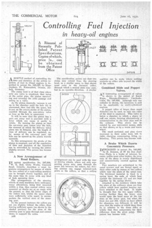
Combined. Slide and Poppet Valves.
AN interesting arrangement of valves is shown in the patent of Karel Rupa, Blansko-Klepacov, Czechoslovakia, No: 347,658. Although only one • Cylinder is shown, the invention is said ' to be applicable to multi-cylindered engines.
A poppet valve of larger than usual diameter can be used, as only one valve of the kind is employed. This valve is below a chamber in which a sleeve or cuff can rotate, forming alternatively a communication to the inlet pipe and to the . exhaust. This sleeve can be rotated by any convenient means, sack as that shown, or by a worm and worm wheel.
The small sectional and plan views represent in their order from left to right, charging, compressing, firing, exhausting. This patent has become void.
A Brake Which Exerts Concentric Pressure.
DESCRIBED in patent No 348,095; by E. Renaux, of 97 bis Rue Joni
troy,Paris, is a brake of interest, because, unlike most other brake's, the pressure of the shoes is evenly distributed and concentrically exerted against the drum.
Two members are articulated in the usual manner and are forced apart at their other ends by means of two rollers which take the place of the usual cam. The frictional material is fixed to a spring band, the ends of which bear against the abutment (7) and are kept together by the spring shown. . Attached to the members which take the place of the ordinary shoes are four rollers which bear against bearing surfaces attached to the band. It might he thought that the two upper rollers, moving farther 'than the lower ones would open the band more at the top than at the lower part, but when the ]inal AA and BB, which we have added for clearness, are followed, it will be seen that the angles at which these lines lie in relation to the drum differ so widely that they compensate for their difference from the pivot point. This Patent has become void.