


A BRITISH-BUILT LOW-Li kFETY COACH CHASSIS.
Page 16
Page 17
Page 18
Page 19
If you've noticed an error in this article please click here to report it so we can fix it.
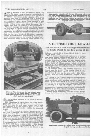
AS OLD readers of this journal will know, we have for many years advocated the building of special passenger chassis as distinct from what may be termed converted goods chassis. We were amongst the first to recognize that it would be essential in the future to diverge considerably from lorry design if safety were to be ensured to the passengers and other users of the road at the higher speeds which were even then becoming more general and with the increase in road congestion.
We have strongly advocated lower-built chassis, the provision of better brakes (preferably servoassisted), the employment of pneumatic tyres and many other features too numerous too recapitulate here. Consequently, we were very pleased to note that in the new low-level Maudslay passenger chassis, which is known as the Safety Model, practically all the features for which we asked have been embodied, and it certainly forms a most vain ible and striking addition to the range of Britishmilt chassis.
This Maudslay is being built in three wheelbases, the main chassis characteristics, however, being the same in each case, except that in one the steering is of the forward type, to give the maximum seating capacity within the required length.
The various chassis are known as the M.L.2 for the 15-ft. wheelbase, this being suitable for open coaches seating 22 passengers ; the M.L.3, with a 16-ft 6-in, wheelbase, which is the forward type and built to carry a single-deck bus body holding 37 people ; and the M.L.4, with a wheelbase of 16 ft. 8 ins, and suitable for saloon buses carrying 30 persons. There are slight differences as regards frame depths and final-drive ratios ; but these will be dealt with later in the article. The length behind the dash (or, in the case of the M.L.3, the total body space) to the _end of the frame is as 1132 follows :—M.L.2, 16 ft. 6 ins. ; •M.L.3, 25 ft. 1i ins. ; 1'tL.4, 19 ft. 7 ins.
One of the most important features is, of course, the frame height. When loaded, this is 2 ft. Oi ins. to the top, and the frame is upswept over the rear axle to the extent of 8 ins. It is also inswept about 4 ins, close to the driver's seat, and, in spite of being built of I-beam-section rolled, structural steel, it is, in a very neat manner and without detracting from its strength, tapered and curved down to the dumb-irons.
The chassis which we actually inspected and tested was the This weighs 2 tons 7 cwt., the distribution being 1 ton 4 cwt. on the front axle and 1 ton 3 cwt. on the rear axle. The M.L.4 model, with its long wheelbase, weighs 2 tons 12 cwt Twisting of the frame is practically obviated by the employment of an unusual number of tubular cross-members, which are best suited to resist torsion. A sub-frame built of channel-section girder serves for the mounting of the engine and gearbox. At the rear it is hung by brackets from one of the cross-members, and forms, with the frame, a rigid construction which prevents torsional stresses being thrown on the four-point-mounted engine and gearbox, which are separate units.
Before going more fully into the chassis design, it may be of interest to refer to tests which. have already been made with an M.L.4 chassis loaded with 2 tons 15 cwt. of iron girders. , On top gear, from running along the level at 3i m.p.h. it wa's, ' within 800 yds. accelerated to 45 m.p.h. We understand that it has climbed Greyhound Hill, outside Kendal, on second gear, and has even tackled, with complete success, Kirkstone Pass, whilst the long hill from Whalley Bridge to Buxton was taken on top gear all the way. As to our .own impressions of the model which we were able to test as a complete 22-seater coach, what struck us most was• the feeling of complete safety which we experienced with the vehicle travelling at speeds up to 40 .m.p.h. Quite apart from the beautifully smooth running, it appeared to hold the road—and in some cases the surface was by no means good—in a remarkable manner, whilst the four-wheel brakes, although enormously powerful, are so nicely balanced and smooth-acting that the rapid deceleration which occurred when they were applied was not uncomfortable. In turning corners at a good speed there was no sign whatever of tail wagging, although we sat in the back seats better to observe anything of this nature which might occur.
The steering—owing, perhaps, partly to the use of roller bearings—is light, and when the vehicle was turned at a, sign-post situated in the centre of a cross-roacK we noted with what little effort
it was controlled, and how it could be turned in a small space, the actual turning circle having a diameter of approximately 52., ft.
To resume our description of the chassis, it is at the front end, well set off by a handsome and distinctive radiator of the honeycomb type, constructed of a white alloy taking a fine polish, the word " bilaudslay " being carried on an enamelled plate on the top tank. For flexibility it is mounted in phosphor-bronze spherical-trunnion bushes. The bonnet is constructed in three pieces and is sharply tapered. The sides are detachable, and, when in position, are securely held by Oda bonnet catches, the hooks of which have concealed springs adjustable for strength, and are neatly mounted on the bonnet sides and engage brackets on the plinths. The material employed for the bonnet is aluminium,
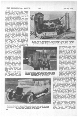
In the power unit the famous Maudslay overhead-camshaft construction, which has been stan dard practice for over 20 years, is retained. The interchangeable valves are set vertically in the detachable head, and are directly operated, through what may be termed piston tappets, from the cams. No means of adjustment is provided, as it has been found quite unnecessary, normal regrinding of the valves making up for the very slight wear which occurs. Particular attention has been devoted to obtaining adequate water cooling around each valve, and there are no common walls to the valve pockets. The sparking plugs are set into the off side of the head at an angle of 60 degrees, and the cylinders form a separate monobloc casting mounted on a cast-aluminium crankcase, the webs of which are extended and joined to carry the Lucas dynamo and starter and the control gear for the magneto. The camshaft is driven through the medium of a vertical shaft enclosed in a tube and bevel driven. From the lower end of the vertical shah a drive is taken, through skew gears, to a cross-shaft, at the off side of which is the Simms magneto with its Vernier coupling; whilst at the near side, and also driven by a flexible coupling, is a large centrifugal pump in a phosphor-bronze casing.
Use is also made of the lower part of the vertical shaft for driving the oil pump, which is of the gear type, and supplies oil under pressure to the crankshaft bearings, the big-ends and the gudgeon pins. The camshaft is also pressure-fed, and the surplus oil from this drains down the casing of the vertical shaft, a second pi oe being provided to remove surplus oil from the back of the head.
The Vore and stroke are 100 mm. and 130 mm. respectively, and at 2,000 r.p.m. the unit develops 60 b.h.p. Cooling is assisted by a twobladed cast-aluminium fan, driven through the medium of a V belt from a pulley on the front end of the crankshaft. Engine speeds up to 2,700 r.p.m. have been attained on the road, and much higher speeds on bench tests. The M.L.3 and M.L.4 types have 110 mm. cylinders developing 70 b.h.p.
The drive is taken through an internal leather faced cone clutch with a Ferodof aced clutch brake carried on a spring secured across the sub-frame. The clutch shaft has a serrated joint at the front end and a Hardy disc at the rear, which takes the drive to the four-speed gearbox, this having ratios of 5 to 1, 2.88 to 1, 1.735 to 1 and direct. In the case of the M.L.2 chassis, with a final reduction of 6 to 1, the corresponding total ratios are 30 to I, 17.28 to 1, 10.38 to 1, 6 to 1, and for the M.L.3 and M.L.4 types, with a reduction of 7 to 1, the ratios are 35 to 1, 20.16 to 1, 12.11 to 1 and 7 to 1.
The gearbox has short stiff shafts mounted on bail or roller bearings, and incorporates a speedometer drive. The swingover control lever is held centrally by light laminated springs and mounted on the frame sidemember.
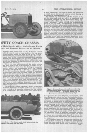
A foot-controlled transmission brake is employed behind the gearbox. This brake is of particular interest, in that with it is combined the servo device for operating the front brakes. The d ru m is a ribbed aluminium casting, with a cast-iron liner, and the shoes, which are faced with Ferodo, have both their pivot pin and operating cam, with its bellcrank lever, mounted on a rocking anchor age. The levers for operating the front-wheel brakes are mounted on a shaft carried underneath this anchorage, and having a double dog keyed to its centre. A sleeve at each side of this dog, and also provided with dog teeth, engages with it, but a certain amount of movement is permitted between the jaws. Each sleeve has a lever coupled to one end of the rocking anchorage by a short tube with ball joints.
The arrangement is such that whichever way the vehicle is travelling the pull on the frontbrake operating rods is always in the same direction. If the anchorage rocks one way it rotates one sleeve, the teeth of which turn the dog, whilst in the case of the other sleeve, which rotates in the opposite direction, the slack between the jaws permits this to move without affecting the double dog. The advantages of the system are that the torsion on the shaft at each side of the double dog is equal, absolute balancing of the braking effect as between the front and rear wheels is assured and, as we have stated, it is equally efficient in forward or reverse. The front brakes are left open so that the condition of the friction material can be examined and the drums, etc., washed out if required.
The shoes are cast-aluminium, ribbed for lightness and cooling, and the hooks for the springs are made of steel bolted to the shoes and also acting as stops for the Ferodo to prevent any possible risk of this shifting on its rivets.
The front brake fulcrum pins and cam spindles are carried direct on the stub axles, which are nickel-chrome stampings.
The sub-frame is inclined so that the engine and gearbox are brought into line with the propeller shaft. This shaft has an enclosed ball bearing universal joint at the front end and a sliding block joint at the rear.
The drive is taken to an underneath worm, of the David Brown F.J. type, in a cast-aluminium casing carried in a forged, double-banjo of great strength, the tubes for which are bored from the solid. The material employed is nickel-chrome, and the axle ends are squared externally for the spring carriers. The springs themselves are underslung, have bushed eyes and, in the case of those for the back axle, are tilted back slightly so that the axle does not rise in the vertical plane but slightly backwards, thus reducing road shocks. The springing is excellent, the rear springs being 54 ins. long, 3 ins. Tilde and practically flat under load, whilst the front springs have a length of 40 ins.
The wheel bearings are Hoffmann rollers with ball thrusts, and the wheels are of the Dunlop detachable-disc type, carrying straight-sided 36-in. by 6-in. pneumatics with twins at the rear. The clearance up to the back axle is 11 ins, and in the back axle 8i ins., whilst the track is 5 ft. 0 ins, between the centres of the rear wheels, and 6 ft. at the front, this wide track giving much better stability.
In the case of the front axle, the material used Is 55-ton steel, and the ends are rounded to take the torsional effect of the brakes. Incidentally, the brake operates' on the rear wheels, cables being used for the connections.
The wheel brakes have high-carbon pressed steel drums, and hardened steel cam plates are used.
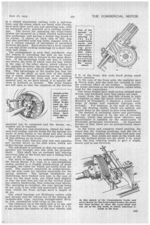
Apart from the fact that this chassis is built throughout to meet the latest requirements of the Ministry of Transport, it displays a sound knowledge of design and combines lightness with strength. For instance, in the case of the rear axle, the floating shafts, which are splined, are turned down in the centre to give even torsion.
The method of excluding water and preventing the loss of lubricant is by the use of reversed threads, which has proved most effective, and maintenance is assisted by the employment of Tecalemit grease-gun lubricators. An important feature is that there are no protuberances above the frame. • In the worm and complete wheel steering, the wheel has six wearing positions, and the use of roller bearings renders the steering both easy and adjustable. Ball joints are used on the track rod, and the inclined pivots are set about in. away from the true centring• points to give a slight, steady pull in one direction.