


Three-function Injection-pump Governor
Page 36
If you've noticed an error in this article please click here to report it so we can fix it.
A Résumé of Recently Published Patent Specifications
EARLY timing for starting from cold is but one of. the provisions afforded by a governor for fuel-injection pumps featuring in patent No. 541,354, in the names of A. F. Sanders, M.I.A.E.; and John Fowler and Co. (Leeds), Ltd., Hunslet, Leeds.
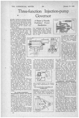
In one embodiment of the invention, as illustrated, a speed-responsive device is incorporated in the drive (by gearing) to the injection pump. Its functions are 'dual; it advances the timing, in normal manner, as engine speed rises, and it controls the fuel delivery at idling speeds. In addition, means are provided for operating t h e advance mechanism independently and irrespective of engine speed when the power unit is cold.
For this purpose a thermostat is employed -and the specification. n a in e s the water jacket as a suitable location for it. It is coupted by suitable linkage to a fork (5) embracing a sleeve on the driven pinion (6) which is free to slide on its shaft. At low engine temperature the pinion is thus held in the fully advanced position, that is, at the extreme left of its axial tiavel. As the temperature rises, the thermostat operates and the pinion moves back to the position shown.
This movement causes it to rotate in relation to the driving pinion (I) because the teeth are helical, and by so doing it retards the injection timing.
On an increase in engine speed, the bob-weight; (2) move outwardly and in doing so slide pinion 6 to the left, as before, advancing the timing. For this action the weights are biased by a relatively strong spring.
It will be observed that there is a clearance (4) between the bob-weight slider and the pinion sleeve. This allows the former sufficient movement for governing the engine at idling speeds, when the weights are biased by the lighter spring. This action is transmitted by a second fork (3) which is coupled to the pump rack rod. For load governing this control is overridden.
TO AVOID STARTER'S WEAKENING EFFECT ON SPARK
ONE of the disadvantages of coil ignition on the modern vehicle is that at the very moment when a good spark is needed, that is, during starting, the coil has to operate. on a reduced voltage, due to the heavy starter current. To overcome this defect is the object of a scheme shown in patent No. 541,037 by H. Muller and W. 'Miller, 47, Piccadilly, Manchester, In this scheme, the primary circuit of the ignition coil (2) inchides a further coil (1), quite separate from the.other and svonnd on a transformer core (4).
The additional coil (I), being wound around iron, offers an impedance to the rise of primary current during normal running, and the circuit is designed with this in view.
The starter cable (3) is, arranged so that one turn embraces the transformer core (4), and, consequently, when theheavy current flows, the core becomes magnetically saturated. In this condi
• tion, the extra coil (1) loses its impedance and, apart from its low ohmic resistance,' its effect vanishes. This per
mits a greater current in the primary circuit, tiles compensating for voltage drop.
TO FACILITATE CLEANING OF LUBRICANT • THERE is no doubt that regular 1 filtration of engine oil is well worth while, though often troublesome to perform, and patent No. 540,981 shows an apparatus intended to facilitate the operation. The patentees are J. F. Zwicky and Air Port Equipment, Ltd., Air p el Works, Wembley.
As is indicated in one of the two accompanying sectional views, the apparatus has a quick-action coupling (4) for' attachment to a pipeline leading to the drainplug . of the engine suinp. A hand pump, not shown, is connected to the exit (3) and, when operated, sucks the oil from the sump, through a cylindrical filter (1), past a one-way valve (2) into pipe 3, whence it flows to a temporary container.
When all the oil has been extracted from the sump, the hand pump is reversed and the filtered oil is returned by valve 5 to the engine, valve 2 then closing to prevcnt any Impurities from being washed back. Valve 5, in the return pipe, has a visual indicator (8) so that the operator may be aware of the presence of oil. By counting the strokes of the hand pump, the quantity of oil in the sump can be estimated. Impurities are retained outside the .filter element (I) and in sumps (6) below it, whilst clean oil is returned by a passage (7).
FRAMELESS ONE-WHEELED PRODUCER-GAS-PLANT TRAILER'
A GAS-PRODUCER, when used with Lis a srealL vehicle, such as a delivery van, can usually be more conveniently trailed than incorporated in the chassis or body, and, in any case, the 'additional weight is in some cases considerable. To minimize this where a traNt is used is the object of a design shown in patent No, 541,313 by D. J. and J. R. Davies, and Worldwin Products, Ltd., Glamorgan.
The design is ingeniously based upon the use of the cooling tubes as a chassis for carrying the producer. The drawing shows, in plan, the triangular frame formed by the cooling tubes, the gas flow being indicated by the arrows. The side tubes (2) are duplicated in upper and lower banks, but they merge into a common cooler and filter (3).
A single castor wheel-(1) is provided at the rear; whilst the front end is pivotally attached at two points (4).