


Injection-pump Adjustment
Page 56
If you've noticed an error in this article please click here to report it so we can fix it.
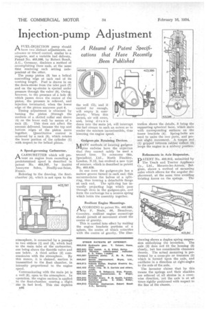
A Msurne of Patent Specifications that Have Recently Been Published A FUEL-INJECTION pump should have two distinct adjustments, an advance or retard control, similar to a magneto, and a variable fuel delivery. Patent No. 403,598, by Robert Bosch, A.G., Germany, disclos.es a method of accomplishing these ends, at the same time rendering each setting independent of the other. The pump piston (3) has a helical controlling edge at each end of its working length. Fuel is drawn in on the down-stroke from the inlet port (7) and on the up-stroke is ejected under pressure through the valve (9). Owing, however, to the presence of a hole (8) which passes down the centre of the piston, the pressurerelieved, and injection terminated,when the lower edge of the piston uncovers port 6. Timing adjustment is obtained by turning the piston (through the medium of a slotted collar and sleeve (4) on the lower end) by means of a rack (2). This does not affect the amount delivered, because the top and bottom edges of the piston move together. Quantitative control is achieved by a rack (5), which rotates the lower portion of the cylinder (I) with respect to the helical piston.
A Speed-governing Carburetter.
PtA CARBURETTER which will prevent an engine from exceeding a predetermined speed is described in patent No. 403,797, by Societo Anonyme Solex, Neuilly-sur-Seine, Prance.
Referring to the drawing, the float.. chamber (4), which is not open to the atmosphere, is connected by a passage. to two orifices (1) and (3), which lead to the main tube of the carburetter, one being above the throttle valve and one below. A third orifice (2) communicates with the atmosphere. By this means, it is claimed, suction is transmitted to the float chamber, in intensity proportional to the engine speed. Communicating with the main jet is a well (5), open to the atmosphere. In operation, the engine suction is applied to the float-chamber, causing, a slight rise in fuel level. This rise depletes
B46
the well (5), and if carried far enough, will empty it completely. When this occurs, air will enter, and, being drawn down into the main jet, will interrupt the fuel stream to such an extent as to render the mixture incombustible, thus lowering the engine speed.
Gudgeon-pin Retaining Devices.
/JAM' methods of locating gudgeon .1.V1pins endwise have the objection that they cannot safely be used a second time. To overcome this, Specialloid, North Finchley, London, N.12, has evolved a new type of retainer, which is described in patent No. 403,628.
In one form the gudgeon-pin has a narrow groove turned in each end: this accommodates the halves of a splitring, thus forming a detachable flange at each end. The split-ring has inwardly projecting lugs which pass through slots in the gudgeon-pin, and form the anchorage for a tension spring which holds the assembly together,
Resilient Engine Mountings.
A cooRDING to patent No. 403,986; 1—by F. Neale, 50, Broadway, Coventry, resilient engine mountings should permit of movement about the centre of gravity, This is carried into effect by making the engine brackets portions of a sphere, the centre of which coincides with the centre of gravity. The illus tration shows the details, 3 being the supporting spherical faces, which mate with corresponding surfaces on the frame brackets (4). Spring-bolts are used to unite the two parts, and permit slight .rnovernent. A torque roil (I) gripped betyi7ecia rubber collars (2) keeps the engine in a midway position.
Refinements in Axle Suspension.
PATENT No. 403,912, submitted by The Truck and Tractor Appliance Co., Ltd., Merxem-lez-Anvers, glum, shows a method of mounting axles which allows for the angular displacement, at the same time avoiding twisting forces on the springs. The drawing shows a duplex spring suspension embodying the invention. The axle ,(3) does not fit the housing (2) closely, but has considerable clearance therein. The actual mounting is performed by a cross-pin or trunnion (I) which is formed upon the axle, and oscillates in a direction at right-angles to the axis of the axle.
The inventor claims that by this means the springs and their shackles are relieved of all strains in a Crosswise direction, yet the axle is at all times rigidly positioned with respect to the line of the chassis,