


Novel Swash-plate Anchorage Scheme
Page 46
If you've noticed an error in this article please click here to report it so we can fix it.
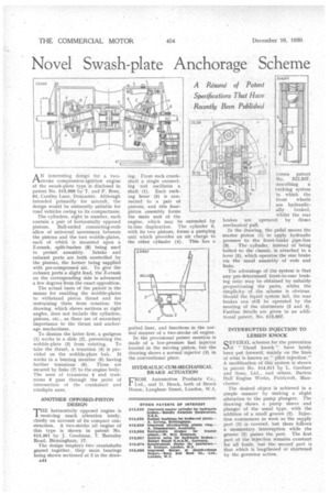
AN interesting design for a twostroke compression-ignition engine of the swash-plate type is disclosed in patent No. 513,999 by T. and F. Rees, 64, Cantley Lane, Doncaster. Although intended primarily for aircraft, the design would be eminently suitable for road vehicles owing to its compactness.
The cylinders, eight in number, each contain a pair of horizontally opposed pistons. Ball-ended connecting-rods allow of universal movement between the pistons and the two wobble-plates, each of which is mounted upon a Z-crank, split-bushes (8) being used to permit assembly. Intake and exhaust ports are both controlled by the pistons, the former being supplied with pre-compressed air. To give the exhaust ports a slight lead, the 2-crank on the corresponding side is advanced a few degrees from the exact opposition.
The actual basis of the patent is the means for enabling the wobble-plates to withstand piston thrust and for restraining them from rotation; the drawing which shows sections at right angles, does not include the cylinders, pistons, etc., as these are of secondary importance to the thrust and anchorage mechanisms.
To dismiss the latter first, a gudgeon (1) works in a slide (2), preventing the wobble-plate (3) from rotating. To take the thrust, a trunnion (4) is provided on the wobble-plate hub. It works in a bearing member (5) having further trunnions (6). These are secured by links (7) to the engine body. The axes of trunnions 4 and trunnions 6 pass through the point of intersection of the crankshaft and crankpin axes.
ANOTHER OPPOSED•PISTON DESIGN
rrHE horizontally opposed engine is 1 receiving much attention lately, chiefly on account of its compact construction. A two-stroke oil engine of this type is shown in patent No. 513,381 by J. Goodman, 7, Barnsley Road, Birmingham, 17.
The design employs two crankshafts geared together, their main bearings being shown sectioned at 2 in the draw a44 ing. From each crankshaft a single connecting rod oscillates a shaft (1). Each rocking lever (5) is connected to a pair of pistons, and this fourpiston assembly forms the main unit of the engine, which may he extended by in-line duplication. The cylinder 6. with its two pistons, forms a pumping unit which provides an air charge to the other cylinder (4). This has a ported liner, and functions in the normal manner of a two-stroke oil engine.
In the provisional patent mention is made of a low-pressure fuel injector located in the moving piston, but the drawing shows a normal injector (3) in the conventional place.
HYDRAULIC-CUACMECHANICAL BRAKE ACTUATION
FROM Autoniotive Products Co., Ltd., and D. f3rock, both of Brock House, Langham Street, London, W.1,
comes patent No. 513,937, describing a braking system in which the front wheels are hydraulic ally braked, whilst the rear brakes are operated by direct mechanical pull.
In the drawing, the pedal moves the master piston (1) to apply hydraulic pressure to the front-brake pipe-line (3). The cylinder, instead of being bolted to the chassis, is attached to a lever (5), which operates the rear brake via the usual assembly of rods and links.
The advantage of the system is that any pre-determined front-to-rear braking ratio may be obtained by suitably proportioning the parts, whilst the simplicity of the scheme is obvious. Should the liquid system fail, the rear brakes can still be operated by the meeting of the abutments (2 and 4). Further details are given in an additional patent, No. 513,957.
INTERRUPTED INJECTION TO LESSEN KNOCK
Q EV 1-ZRAL schemes for the prevention
of"Diesel knock" have lately been -put forward, mainly on the lines of what is known as " pilot injection." A modification of this system is shown in patent No. 514,011 by L. Gardner and Sons. Ltd., and others, Barton Hall Engine Works, Patricroft, Manchester.
The desired object is achieved in a simple manner by making a slight alteration to the pump plungers. The drawing shows a pump sleeve and plunger of the usual type, with the addition of a Small groove (2). Injection commences as soon as the supply port (1) is covered, but there follows a momentary interruption while the groove (2) passes the port. The first part of the injection remains constant for all loads, but the second part is that which is lengthened or shortened by the governor action.