 1
1 2
2 3
3 4
4 5
5 6
6 7
7 8
8 9
9 10
10 11
11 12
12 13
13 14
14 15
15 16
16 17
17 18
18 19
19 20
20 21
21 22
22 23
23 24
24 25
25 26
26 27
27 28
28 29
29 30
30 31
31 32
32 33
33 34
34 35
35 36
36 37
37 38
38 39
39 40
40 41
41 42
42 43
43 44
44 45
45 46
46 47
47 48
48 49
49 50
50 51
51 52
52 53
53 54
54 55
55 56
56 57
57 58
58 59
59 60
60 61
61 62
62 63
63 64
64 65
65 66
66 67
67 68
68 69
69 70
70 71
71 72
72 73
73 74
74 75
75 76
76 77
77 78
78 79
79 80
80 81
81 82
82 83
83 84
84 85
85 86
86 87
87 88
88 89
89 90
90 91
91 92
92 93
93 94
94 95
95 96
96 97
97 98
98 99
99 100
100 101
101 102
102 103
103 104
104 105
105 106
106 107
107 108
108 109
109 110
110 111
111 112
112 113
113 114
114 115
115 116
116 117
117 118
118 119
119 120
120 121
121 122
122 123
123 124
124 125
125 126
126 127
127 128
128 129
129 130
130 131
131 132
132 133
133 134
134 135
135 136
136 137
137 138
138 139
139 140
140 141
141 142
142 143
143 144
144 145
145 146
146 147
147 148
148 149
149 150
150 151
151 152
152 153
153 154
154 155
155 156
156 157
157 158
158 159
159 160
160 161
161 162
162 163
163 164
164 165
165 166
166 167
167 168
168 169
169 170
170 171
171 172
172 173
173 174
174 175
175 176
176 177
177 178
178 179
179 180
180 TENDENCIES IN CHASSIS DESIGN
Page 94
Page 95
If you've noticed an error in this article please click here to report it so we can fix it.
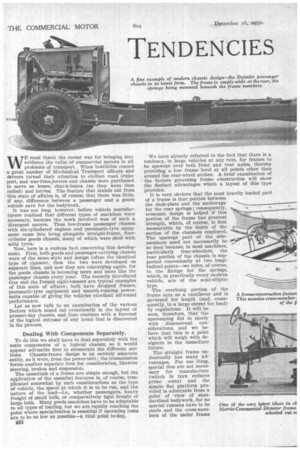
WYE must thank the recent war for bringing into evidence the value of commercial motors in all problems of transport. When hostilities ceased a great number of Mechanical Transport officers and
thivers turned their attention to civilian road transport, and war-tirne.lorries and chassis were purchased to serve as buses, char-5.-bancs (as they were then called) and lorries. The feature that stands out from this state of affairs is, of course, that there was little, If any, difference between a passenger and a goods vehicle save for the bodywork.
It was not long, however, before vehicle manufacturers realized that different types of machines were necessary, because the work involved was of such a divergent nature. Thus low-frame passenger chassis with six-cylindered engines and pneumatic-tyre equip ment came into being alongside straight-frame, fourcylinder goods chassis, many of which were shod with solid tyres.
Now, here is a curious fact concerning this development. First, both goods and passenger-carrying chassis were of the same style and design (often the identical type of chassis), then the two were developed on separate lines, and now they are converging again, for the goods chassis is becoming more and more like the passenger chassis every year. The recently introduced Guy and the Dennis eight-tonners are typical examples of this state of affairs; both have dropped frames, pneumatic-tyre equipment and smooth-running powerunits capable of giving the vehicles excellent all-round performance.
Let us now Win to an examination of the various factors which stand out prominently in the layout of present-day chassis, and then continue with a forecast of the logical outcome of any trend that is discovered in the process,
Dealing With Components Separately.
To do this we shall nave to deal separately with the main components of a typical chassis, so it would appear advisable first to enumerate the different sections. 'Chassis-frame design is an entirely separate entity, as it were, from the power-unit ; the transmission forms another separate item for consideration, likewise steering, brakes and suspension.
The essentials of a frame are simple enough, but the application of the essential features is, of course, complicated somewhat by such considerations as the type of vehicle, the speed at which it is to be rim, and the nature of the load—i.e., whether passengers, heavy freight of small bulk, or comparatively light freight of large bulk. Many goods machines have to be adaptable to all types of loading, but we are rapidly reaching the point where specialization is essential if operating costs are to be as low as possible—a vital point to-day, in We have already referred to the fact that there is a tendency, in large vehicles at any rate, for frames to be upswept over both front and rear axles, thereby providing a low frame level at all points other than around the rear-wheel arches. A brief examination of . the factors governing frame construction will show the distinct advantages which a layout of this type provides. It is very obvious that the most heavily loaded part of a frame is that portion between the dash-plate and the anchorage for the rear springs; consequently, economic design is helped if this portion of the frame has greatest strength, which, of course, is first measurable by the depth of the section of the channels employed. The upswept part of the sidemembers need not necessarily be so deep because, in most machines, particularly four-wheelers, the rear portion of the chassis is supported conveniently at two longitudinal points—we refer, of course, to the fixings for the springs, which, in practically every modern vehicle, are of the semi-elliptic type.
The overhung portion of the frame acts as a cantilever and is governed for length (and, consequently, to a large extent for load) by regulations. It will be seen, therefore, that the upsweeping fits in nicely with dimensional considerations, and we believe that this is a point which will weigh with designers in the immediate future.
The straight frame undoubtedly has many advantages. For one thing, special dies are not necessary for manufacture (which in turn reduces prime costs) and the simple flat platform provided is admirable from a point of view of standardized bodywork, for no special runners have to be made and the cross-members of the under frame of the bodywork can all be of standardized pattern. In practice, too, the fiat-platform lorry has many advantages peculiar to the type, especially in small and medium-sized •ranges of vehicles where wheelarches would cut into the platform space to an inconvenient extent. Against this, however, one may quote the fact that most of the light vehicles are hand loaded, whereas in the large vehicles some form of crane or hoisting gear is often employed.
One point concerning the effect of loading upon chassis design is worth enlarging upon. When heavy goods are being handled it is only natural that they should first of all be rested on the rear extremity of the platform (in the case of a van this is essential and, although in a drop-side lorry provision is made for side loading, it often happens that it is inconvenient to bring the vehicle into position alongside the freight). This, of course, means heavy loads on the cantilever (or overhung) portion ,of the frame, so that even in the event of dropped frames becoming general, the strength of the rear portion will have to be sufficient to meet the demands of concentrated loads at the rearmost extremity.
With dropped frames all sorts of possibilities present themselves. For instance, the use of small-wheel trolleysit in conjunction with a winch gear and a short ramp would form an excellent method of loading and unloading heavy packages, the low platform helping to cut down the length of the ramp and the energy which has to be expended to lift the material from the ground to platform height.
From an examination of many 1931 goods and passenger chassis a great advance in cross-bracing of the frame is apparent. Distortion .due to an uneven distribution of payload should be greatly reduced because cross-mem
bers have, in the main, been increased both in size and in number, most chassis having _ at least four substantial cross-members, located along the portion of the frame, devoted to carrying the pay-load. While dealihg with this point about' cross-members the forward part of the chassis, i.e., around the engine, clutch and gearbox, seems to be, In certain instances, partially, neglected. Doubtless this state of affairs will be rectified in time, as have been Other features of frame design in past years.
Strengthening the Forward End of the Frame.
It would appear to be essential for a really successful design to incorporate some form of tie at a point no greater than, say, 5 ft. from the dumbirons' support in order to avoid the possibility of the side-members generating an in-and-out motion under certain extreme conditions of load. In a number of cases the rear engine support forms a tie of sorts, but as the unit is very often mounted on rubber or some other insulating material the value as a tie is sometimes reduced.
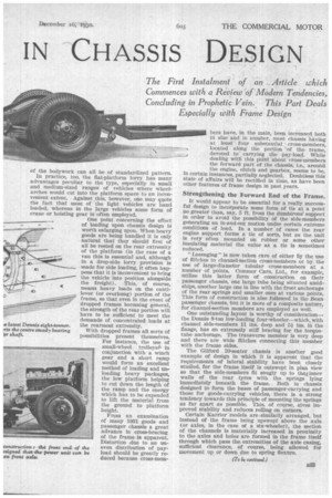
" Lozenging" is now taken care of either by the use of flitches to channel-section cross-members or by the use of large-diameter tubular cross-members at a number of points. Commer Cars, Ltd., for example, utilize this latter form of construction on their passenger chassis, one large tube being situated amidships, another large one in line with the front anchorage of the rear springs and smaller ones at various points. This form of construction is also followed in the Bean passenger chassis, but it is more of a composite nature, for channel-section members are employed as well.
One outstanding layout is worthy of consideration— the Dennis 8-ton low-loading four-wheeler—which, with channel side-members 11 ins, deep and 54 ins, in the flange, has an extremely stiff bracing for the torquetube anchorage. The transverse member is very deep and there are wide flitches connecting this member with the frame sides.
The Gilford 20-seater chassis is another good example of design in which it is apparent that the requirements of lateral stability have been closely studied, for the frame itself is outswept in plan view so that the side-members fit snugly up to thelinner walls of the rear tyres with the springs lying immediately beneath the frame. Both in chassis designed to form the bases of passenger-carrying and those for goods-carrying vehicles, there is a strong tendency towards this principle of mounting the springs as far apart as possible. This, of course, gives improved stability and reduces rolling on corners.
Certain Karrier models are similarly arranged, but instead of the frame being upswept above the axle (or axles, in the case of a six-wheeler), the section of the channels is materially increased in proximity to the axles and holes are formed in the frame itself through which pass the extremities of the axle casing, sufficient clearance, of course, being allowed for movement up or down due to spring flexure.