


Patents Completed.
Page 24
If you've noticed an error in this article please click here to report it so we can fix it.
Complete specifications of the following patents will be sent to any address in the United Kingdom upon receipt of eightpence per copy at the Sale Branch, Patent Office, Holborn, W.C.
SPOUT FOR PETROL CAN.—Cox. —No. 26.148, dated 3rd June, 1909.— This invention relates to a spout that may be attached to petrol cans in order to enable the petrol to be poured into vessels having small openings. The spout comprises a cap which is adapted to be screwed on to the nozzle of the petrol can and which is provided with an internal screw thread which is
adapted to receive a tap having a long spout. The cap contains a screen or filter which is held in place by a ring or washer. At one side of the cap an opening is provided to admit air to the interior so as to allow the liquid to pour more freely. This opening may be in the form of a tube that is bent at right angles and extends into the can.
EXHAUST VALVE.Koven.—Xo. 12,971, dated 2nd June, 1909.—According to this invention, the exhaust valve is arranged to be cooled by a cooling fluid. With this end in view, the valve is made hollow and is provided with two passages within its stern. The inlet passage extends into the hollow head of the valve and is so positioned as to cause the cooling fluid to enter the valve head in a tangential direction thus pro ducing a whirling of the cooling fluid. The valve stein is provided with suitable couplings and flexible tubes, whereby it may he connected to the supply and exhaust. The supply tube is provided With a screen for the purpose of preventing the small passages in the valve stem from becoming clogged by any impurities contained in the cooling medium.
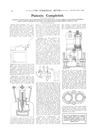
CONTROL OF AIR SUPPLY TO CARBURETTERS. — Rhodes. — No. 576, dated 9th January, 1909.—This invention relates to a device for controlling the admissien of air to a carburetter. which latter supplies gas to a gasometer. The device comprises a slide valve which is adapted to control a circular passage having a V-shaped groove. The slide valve is connected to a rod which extends up through the casing and is provided with two collars
and adjustable nuts. The collars engage an arm which is pivoted at one end to a bracket which is, in turn, secured to the casing of the device, and. at the other end, is connected to a rod that is adapted to be raised by the gasometer when the latter is nearly full, so that further movement of the latter will cause the slide valve to be closed
and will thus stop the supply of air to the carburetter. At the other end of the circular passage an ordinary clack valve or non-return valve is provided. This valve is normally kept off its seating by the pressure of air passing to the carburetter, but, on the air being shut off, the non-return valve will close and will thus prevent any return of the air or gas from the carburetter. It will be seen that, owing to the provision of the V-shaped groove, the supply of air can be gradually reduced to an extremelysmall quantity as the valve moves upward, and, at the same time, permits of gradually increasing the supply of air to be supplied to the carburetter as the bell of the gasometer lowers. A safety valve is also provided which is of the poppet type; the spindle of this valve has collars and adjustable nuts which engage the before-mentioned pivoted arm, so that, on the bell of the gasometer rising beyond the predetermined limits, the safety valve will be opened and the air will escape to atmosphere.
INTERNAL COMBUSTION ENGINE. — Moses and Another. — No. 24.371, dated 12th November, 1908.— The object of this invention is to enable the engine to be dismantled readily for inspection and cleaning purposes. The cylinder is rotated by the crankshaft through suitable gearing, and it has a conical portion at the head which fits a similarly-coned portion of the en g'ne casing. At the lower end of the cylinder, a flange is provided which rests on ball bearings that are yieldingly supported from the engine-casing by means of stout springs. The head of the cylinder is also provided with ball bearings, one race member of which is carried by adjustable screws, so that the position of the cylinder may be adjusted to allow for wear. The cylinder is provided with diametrically-opposite ports which are adapted to register at the proper moment with inlet and exhaust ports provided in the engine casing. Two exhaust ports are provided which communicate with a main exhaust in which are arranged sleeve valves. These valves are arranged so that they only open one exhaust passage of each cylinder at one time.