


THE COMPARATIVE MEE TS OF TWO-WHEEL AND
Page 42
Page 43
Page 44
Page 45
If you've noticed an error in this article please click here to report it so we can fix it.
FOUR -WHEEL DRIVE Fl IR RIGID SIX-WHEELERS C. ONSIDERATIONS of weight, complication and expense_ obviously favour the use of a trailing axle on rigid six-wheeled or eight-wheeled vehicles. The additional tractive power of the machine equipped with double-drive may, however, give it aft advantage. When one attempts -to analyse the various conditions for -which each of. the two types is the better Suited,
the matter, becomes less simple. ,
For Main-road goods transport, it is generally agreed that a single drivingaxle is adequate. In normal circumstances, the adhesion between road and tyre is stilhicient for two wheels to afford ample traction, and all hills likely to be encountered can be climbed without wheel spin. No loss in average tyre life isshown by dispensing with the second driving axle; indeed, if no intelmediate differential be employed in the double drive, there may be a gain. Furthermore, the use of double drive generally shows a loss. of efficiency, worms accounting for a proportion of this, and sliding splines for part of the remainder.
Single drive, in the main, is also suitable for sixwheeled coach work, but owing to the lighter loading of the bogie, to a somewhat less degree. Six-wheeled buses, on the other hand, for really efficient operation should have two driving axles. Rapid acceleration, repeatedly called upon, is important on stage-carriage service, whilst frequently the co-efficient of friction between tyre and road on slippery town streets is low.
In addition, the proportion of weight on the front axle must be high to give certain steering even when the vehicle is empty. Consequently, the bogie loading may often be too light to preclude the possibility of wheel spin, if only the one axle be relied upon for traction purposes.
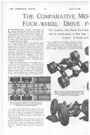
Although trailing-axle six-wheeled goods vehicles are operating regularly with reasonable success under conditions which involve the frequent negotiation of secondary roads, steep hills and sometimes soft ground, these are conditions under which the double-drive machine would be expected to give much better service.
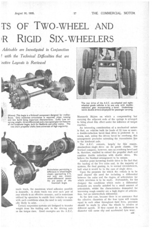
Tipping lorries are at a special disadvantage when extricating themselves from a difficult position after. tipping. With no load on board and the wheels possibly_ dug in through reversing• over a .well-used and badly, (Above) This bogie is a Kirkstall component designed for trolleybuses. Only moderate articulation is required, silent running and low build being important characteristics. (Left) Low unsprung weight, three differentials and a two-speed gear are features of the Unipower bogie, built for Bedfords and other makes. The two short propeller shafts have universals of high angularity.
made track, the maximum wheel adhesion possible is desirable. A chain track run over each pair of rear wheels is an effective measure, and is sometimes utilized by operators to enable their vehicles to cope with such conditions when the need is only occasionally likely to arise.
Certain suspension systems are designed to transfer weight from the trailing axle to the driving axle as the torque rises. Good examples are the A.E.C. Mammoth Majors on which a compensating bar carrying the adjacent ends of the springs is arranged to bring about this effect under the influence of torque reaction.
An interesting consideration of a mechanical nature is that, on vehicles built for loads of 12 tons or more, a double-reduction bevel final drive is preferred to a worm, and, unless the driven bevel be overhung, this arrangement precludes extending the transmission line to the hindmost axle.
• The A.E.C. concern, largely for this reason, • standardizes single drive on its goods chassis. The Sentinel company, .however, uses an overhung bevel and is, therefore, enabled to extend the propeller shaft and combine double reduction with double drive. We believe the Sentinel arrangement to be unique.
Another point favouring double drive is the fact that the loading of the live axles and, in the majority of systems, the final gearing, is, in normal circumstances, half what it would be in the case of single drive.
Upon the purposes for which the vehicle is to be used depend the need for including a differential between the axles and the degree of articulation for which provision is to be made. Fortunately, for the designer the conditions which make a differential desirable are usually satisfied by a small amount of articulatidn, whilst the characteristics demanded for traversing rough country are a high degree of articulation, but no intermediate differential.
In the first case, because there is no assurance that the effective diameters of the four tyres will remain equal to each other throughout their lives, provision should be made to allow the wheels to revolve at different speeds. If they cannot do so, differences in diameter will cause slip and accelerated tyre wear.
In the second case, the machine during negotiation of an irregular surface is almost sure to get one wheel on a bad lie. Then, if the drive be not independently conveyed to each axle—that is, if the drive to one pair of wheels be dependent on the grip of the other pair—the wheel with imperfect adhesion will spin and no torque will be transmitted to the others.
Thus the right designs for main-road work and for cross-country work are clear, but, because in this matter it is not possible to compromise, the ideal system for both cannot -be attained unless a differential lock be incorporated, and for obscure reasons this is rarely done.
Intermediate Differentials and Tyre Wear.
Makers who build bogies without intermediate differentials maintain that the tyre wear, on main roads is not appreciably increased, and those whose products are thus equipped point out that the vehicle' is under little disadvantage in respect of wheel spin on soft ground. Practice shows that the first claim is justified provided that reasonable precautions be taken to preserve equality of tyre diameter. Likewise the four-wheel-drive six-wheeler with an intermediate differential is superior to the trailing-axle machine on really difficult surfaces, but, of course, just as on the latter type, chair tracks can be used for really bad conditions, and the employment of twin tyres diminishes' the tendency of the wheels to spin.
Much ingenuity has been displayed in designing fourwheel-drive bogies, and there is a surprising variety of methods employed. Obviously in comparing the systems —as with double and single' drive--consideration must be -paid to the purposes for which they have been planned, their cost and their weight. Degree of articulation is an important factor which largely governs the choice of layout. For example, a. short intermediate shaft, incorporating one or more universals of orthodox angularity may limit the relative up-anddown motion of the axles. This is by no means always the case, however, and is inseparably connected with the layout of the suspension system. In this connection it should.be remembered that it is highly undesirable, largely because cornering characteristics are impaired, to exceed the minimum practicable distance betweenroad-wheel cente4s.
A System Favoured on Passenger Vehicles.
The system employing a short intermediate shaft is probably the simplest and is generally used on passenger vehicles. It is easily adaptable to either the overtype or undersiung worm and presents no great difficulty in the way of incorporating an intermediate differential. This component need not be of any great hulk, being easily housed in one or other of the axle casings. The underslung worm is generally used for passeager carrying, because of its low position and silence. Examples are seen in A.E.C. and Leyland buses, whilst applications of this method with overtype worm: are 'in certain models of the ' Leyland Hippo and Octopus ranges, the Morris
Commercial and Thornycroft cross-country models and the last-named concern's Amazon and Tartar machines.
It can also be employed with bevel drive, but not in quite such a straightforward manner, as, obviously the propeller shaft cannot be extended to the second axle without interruption.
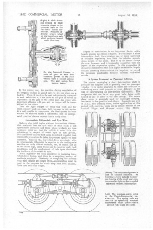
An instance in this case is the Fordson S.ussex. On this machine the first crown wheel drives a second bevel pinion set on a horizontal axis not quite diametrically opposite to it, and carrying a shaft with a universal joint at its front end and housed in a torque tube having a third bevel at its rear end, which, in turn, meshes with a reversed crown wheel on the hindmost axle.
Doubtless anxious for the welfare of the first pinion, the designer of this drive has adopted the unusual but ingenious practice of mounting a third crown wheel on the first axle, facing the first crown wheel and free to revolve in the opposite direction thereto, Its function is taking nearly the whole burden of transmitting torque to the second pinion and materially easing the loading of the bearings of the four wheels concerned. That of the loose Wheel, incidentally, is the combined ball and rollertype taking radial and axial forces.
A Universal Joint Providing Wide Angularity.
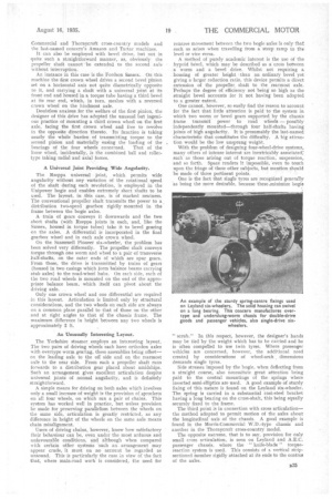
The Rzeppa universal joint, which permits wide angularity without any variation of the rotational speed of the shaft during each revolution, is employed in the Unipower bogie and enables extremely short shafts to be used. The layout, in this case, is of marked neatness. The conventional propeller shaft transmits the power to a. distribution two-speed gearbox rigidly mounted in the frame between the bogie axles.
A train of gears conveys it downwards and the two short shafts (with Rzeppa joints in each, and, like the Sussex, housed in torque tubes) take it to bevel gearing on the axles. A differential is incorporated in the final gearbox wheel and in each axle crown wheel.
On the Scammell Pioneer six-wheeler, the problem has been solved very differently. The propeller shaft conveys torque through one worm and wheel to a pair of transverse half-shafts, on the outer ends of which are spur gears. From these, the drive is transmitted by trains of gears (housed in two casings which form balance beams carrying stub axles) to the road-wheel hubs. On each side, each of the two ruad wheels is mounted on the end of the appropriate balance beam, which itself can pivot about the driving axle.
Only one crown wheel and one differential are required in this layout. Articulation is limited only by structural considerations, and the tw-o wheels on each side are always on a common plane parallel to that of those on the other and at right angles to that of the chassis frame. The maximum difference in height between any two wheels is approximately 2 An Unusually Interesting Layout.
The Yorkshire steamer employs an interesting layout. The two pairs of driving wheels each have orthodox axles with overtype worm gearing, these assemblies being offset— on the leading axle to the off side and on the rearmost axle to the near side. From each a propeller shaft runs forwards to a distribution gear placed about amidships. Such an arrangement gives excellent articulation despite universal joints of normal angularity, and is definitely straightforward.
A simple means for driving on both axles which involves only a small increase of weight is the provision of sprockets on all four wheels, on which run a pair of chains. This system has worked well in practice, but unless provision be made for preserving parallelism between the wheels on the same side, articulation is greatly restricted, as any difference in height of the wheels on the same axle means chain misalignment.
Users of driving chains,, however, know how satisfactory their behaviour can be, even under the most arduous and unfavourable conditions, and although when compared with certain other systems such an arrangement may appear crude, it must on no account be regarded as unsound. This is particularly the case ;n view of the fact that, where main-road work is considered, the need for relative movement between the two bogie axles is only that such as arises when travelling from a steep ramp to the level or vice Versa.
A method of 'purely academicinterest is the use of the hypoid bevel, which may be described as a cross between . a worm and a bevel drive. Whilst not requiring a housing of greater height than an ordinary bevel yet giving a larger reduction ratio, this device permits a direct extension of the propeller, shaft to the rearmost axle. Perhaps the degree of efficiency not being so high as the straight bevel accounts for it not having been adopted to a greater extent.
One cannot, however, so easily find the reason to account for the fact that little attention is paid to the system in which two worm Or bevel gears supported by the chassis frame transmit power to road wheels — possibly independently mounted—through four half-shafts having joints of high angularity. It is presumably the last-named characteristic that constitutes the difficulty. A big attraction would be the low unsprung weight.
With the problem of designing four-wheel-drive systems. many others of intense interest are inextricably associated; such as those arising out of torque reaction, suspension, and so forth. Space renders it impossible, 'even to touch upon the fringe of these other subjects, but mention should be made of three pertinent paints. One is the fact that single tyres are recognized generally as being the more desirable, because these.,minimize bogie
" scrub." In this respect, however, the designer's hands may be tied by the weight which has to be carried and he is often compelled to use twin tyres. Where passenger vehicles are concerned, however, the additional need created by considerations of wheel-arch., dimensions demands single tyres.
Side stresses imposed by the bogie, when deflecting from a straight course, also necessitate great attention being paid to the central mountings of the springs where inverted semi-elliptics are used. A good example of sturdy fixing of this nature is found on the Leyland six-wheeler. The spring is carried in a substantial east-steel bracket having a long bearing on the cross-shaft, this being equally securely fixed to the frame. The third point is in connection with cross articulation— the method adopted to permit motion of the axles about the longitudinal axis of the chassis. A good example is found in the Morris-Commercial W.D.-type chassis and another in the Thornycroft cross-country model.
The opposite extreme, that is to say, provision for only small cross articulation, is seen on Leyland and A.E.C. passenger chassis, where the -" knife-blade " torquereaction system is used. This consists of a vertical stripsectioned member rigidly attached at its ends to the centres of the axles.