


A NEW AND UNUSUAL MUNICIPAL APPLIANCE.
Page 62
Page 63
If you've noticed an error in this article please click here to report it so we can fix it.
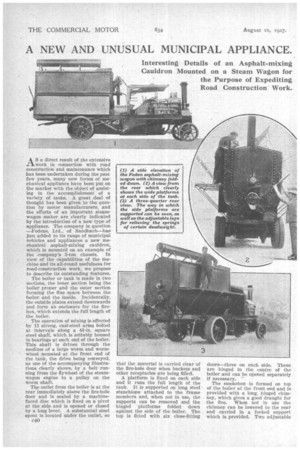
Interesting Details of an Asphalt-mixing Cauldron Mounted on a Steam Wagon for the Purpose of Expediting Road Construction Work.
AS a direct result of the extensive work in connection with road construction and maintenance which has been undertaken (luring the past few years, many new forms of mechanical appliance have been put on the market with the object of assisting in the accomplishment of a variety of tasks. A great deal of thought has been given to the question by motor manufacturers, and the efforts of an important steam wagon maker are clearly indicated by the introduction of a new type of appliance. The company in question ---loodens, Ltd., of Sandbach—has just added to its range of municipal vehicles and appliances a new mechanical asphalt-mixing cauldron, which is mounted on an example of the company's 5-ton chassis. In view of the capabilities of the machine and its all-round usefulness for road-construction work, we propose to describe its outstanding features.
The boiler or tank is made in two sections, the inner section being the boiler proper and tlie outer section forming the flue space between the boiler and the inside. Incidentally, the outside plates extend downwards and form an enclosure for the firebox, which extends the full 'length of the boiler.
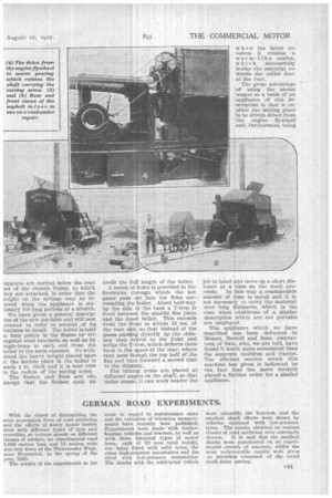
The operation of mixing is effected by 11 strong, cast-steel arms bolted at intervals along a 41-in, square steel shaft, which is suitably housed in bearings at each end of the boiler. This shalt is driven through the medium of a large worm and wormwheel mounted at the front end of the tank, the drive being conveyed, as one of the accompanying illustrations clearly shows, by a belt running from the flywheel of the steamwagon engine to a pulley on the worm shaft.
The outlet from the boiler is at the rear immediately above the fire-hole door and is sealed by a machinefaced disc which is fixed on a pivot at the side and is opened or closed by a long lever. A substantial steel spout is located under the outlet, so c40 that the material is carried clear of the fire-hole door when buckets and other receptacles are being filled.
A platform is fixed on each side and it runs the full length of the tank. It is supported on long steel . stanchions attached to the frame members and, when not in use, the supports can be removed and the hinged 'platforms folded down against the side of the boiler. The top is fitted with six close-flitting doors—three on each side. These are hinged in the centre of the boiler and can be opened separately if necessary.
The smokebox is formed on top of the boiler at the front end and is provided with a long, binged chimney, which gives a good draught for the fire. When not in use the chimney can be lowered to the rear and carried in a forked support which is provided. Two adjustable
;imports are carried below the. rear md of the chassis frame, to which ley are attached, in order that the veight on the springs may be reieved when the appliance is sta:ionary for long periods at a stretch.
We have given a general descrip'Ion of the new machine and will now 2roceed to refer to several of its Peatures in detail. The boiler is held it four points in the frame . by triingular steel brackets, as well as by mgle-irons at each end from the boiler to the main channel. To withstand the heavy weight placedupon it, the bottom plate in the boiler is made in. thick and it is bent true to the radius of the mixing arms.
The firebox and flues are one, except that the firebox arch ex
tends the full length of the boiler.
A series of holes is provided in the firebricks through which the hot gases pass out into the flues surrounding the boiler'. About half-way up the side of the tank a T-iron is fixed between the outside flue plate and the inner boiler. This extends from the front to Within 18 ins, of the rear e d, so that instead of the gases pa ' ig directly up the chimney they travel to the front and strike the T-Iron, which deflects them back to the space at the rear, where they pass though the top half of the flue and then forward a second time to the Chimney.
The mixing . arms are placed at different angles on the shaft, so that under steam, it can work nearer the w hen the latter revolves it creates a worm-like motion, which successfully works the material towards the outlet door at the rear.
The great advantage of using the steam wagon as a basis of an appliance of this description is that it enables the mixing plant to be driven direct from the engine. flywheel and, furthermore, being job in hand and move up a short distance at a time as the work proceeds. In this way a considerable amount of time is saved and it is not necessary to carry the material over long distances, which is the case when cauldrons of a similar description which are not portable are employed.
The appliance which we have described has been delivered to Messrs. Bethell and Sons, contractors, of Sale, who, we are told, have found it much more economical than the separate cauldron and tractor. The efficient service which this machine has given is indicated by The fact that the users recently placed a further order for a similar appliance.