


CRANE EQUII 'OR LORRIES.
Page 54
Page 55
If you've noticed an error in this article please click here to report it so we can fix it.
A Review of Some of the Possibl for Special Work can be lereby. Better Vehicle Adaptability aut Undue Complication.
ONE of the most important and difficult problems of the haulier and carrier, especially in the case of those concerned in the transport of heavy goods, is the question of loading. Some haulage costs, for instance, are based almost entirely upon the "waiting charges" for the time during which loading and unloading are carried out—the actual mileage of the vehicle does not, in quite a large number of cases, have a great relationship to the total cost of a job.
-Now anything that can .be done to permit a reduction in this waste of time should, in the end, amply repay the initial cost—if this be a reasonable amount—and the maintenance costs. Of course, it must be borne in mind, too, that the classes of work undertaken by both large and small vehicles vary enormously and so the means required to facilitate -loading and unloading must also vary accordingly. Take as an instance a big, rigid-frame, six-wheeled lorry which one day is transporting a number of packages containing repetition products of an engineering works each weighing in the neighbourhood of 1 cwt.; the next day, perhaps, a large casting may have to be transported from London to one of the northern manufacturing centres. This disparity is an extreme case, but it is quite obvious that a special loading device would be required by the large casting (which may weigh as much as 4 tons or 5 tons), whilst two men could lift with reasonable ease packages of 1 cwt. and load them on to a platform, say, 3 ft. high, quite as fast as a crane could work when handling one package at a time.
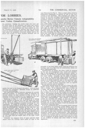
The foregoing two instances do not really come within the scope of this article. Actually, the medium weight and more bulky packages, such as the products of some of the textile manufacturing concerns, certain types of engineering requisites, packing eases containing Products for transhipment abroad, etc., each weighing more than can be handled with ease by two men, are the types of load that require some mobile means forconvenient handling.
Granted that most clocks and large works have cranes located iii convenient positions for loading and -unloading, or else have platforms arranged at the platform height of the lorries in general use, there is, however, a class of work which demands travelling facilities for loading and unloading. There are, in fact, many in stances where a comparatively large number of men is required for several hours, when two men and a suitable crane would actually suffice, the time taken when using such means being very considerably less than if all the pay load had to be man-handled. When it comes actually to the layout of a lifting gear for attachment to a lorry, one is confronted by so many exigencies of the service to which a vehicle will be put, that the question really resolves itself into pro 032 viding a gear that is specially suitable to the main class of work which the vehicle will be called upon to undertake. Some loads necessarily demand that the vehicles should be weatherproof, and in such instances the vehicle must, therefore, be totally enclosed. This, then, presents an entirely different problem from one where the loading space available is not even enclosed , at the sides, such as that in the vehicle depicted in Fig. 3.
Considering the matter now in more detail, let us first turn our attention to the large enclosed-van-type of body. This would seem to be the easiest type of vehicle to equip satisfactorily with lifting gear, as stanchions are already erected to retain the head. These supports would, of course, have to be strengthened considerably or a much more robust structure erected.
In Fig. 4 the rudiments of such a scheme are given. Two rails of channel section are arranged to run longitudinally along the top of the body and are suitably supported by either channel or girder-section stanchions. Rough calculations will show that the weight of these parts need not be excessive, neither is much space taken up by them in order satisfactorily to deal with weights up to, say, 15 cwt. Within the two channel-section girders are situated two pairs of rollers mounted upon another framework, on the rear end of which an axle and block and tackle are fitted in such a manner than the secondary structure can he moved longitudinally along the vehicle with or without its load. Thus all but the front end of the body can be loaded absolutely directly—i.e., the packages can be placed definitely in their position on the platform. Taking the worst—coal—the load can be lifted clear of the platform, the block and tackle, complete with its structure, rolled forward, the load dropped on to the platform and then pushed up into the foremost position. If desired, the top structure could be carried forward above the cab, which would thus allow the secondary structure, which carries the block and tackle, to move farther forward and so enable the load to be dropped into place. For all other positions the movement afforded would be sufficient to avoid man-handling.
The open-sided vehicle however, presents an entirely different problem. A structure could, if required, be erected similar to that outlined in Fig. 4, but it is doubtful whether it would fit in so compactly and conveniently as some form of jib-type lifting gear.
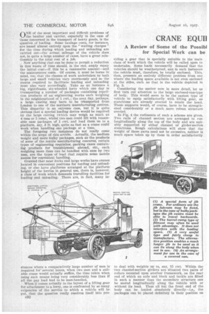
Referring to Fig. 1, a jf5 is pivoted on a sliding block capable of moving fore and aft along the body sides, which, in effect, serves to alter the angularity of the jib, thus avoiding excessive overhang for this component. It would be necessary in many cams to alter the angular position of the jib as well, so a handle could be provided for winding up the arm into any desired position. There must, however, be a stop placed in such a way that the jib does not pass the dead-centre position. This form of gear should prove very simple to operate and construct, but its range of usefulness would, it is feared, be somewhat limlted, as lest; than half the length only of the body would be covered.
Probably the simplest form of gear and the most useful from the average user's point of view is the
type illustrated in Fig. 3. Here a single pillar of fairly substantial dimensions is erected at one of the rear corners of the platform. The structure can easily be braced by two ties arranged longitudinally and transversely or held by a special cast bracket. It will be necessary, however, to carry the pillar below the platform in order to avoid interference with loading from the rear. On a bracket extending rearwards a swivel gear could easily be fitted, with a jib capable of being raised or lowered, possibly by means of a cable passing over a pulley on the main pillar. All that has to be done then in order to lift the load is to extend the jib sufficiently and move it around into the desired poSition, when, by turning the handle attached to the jib, thus operating the sling chain, the load would be lifted and could then be swung into a convenient position by hand. This is probably one of the simplest forms possible. It would, perhaps, simplify the con
struction if the main pillar itself could be turned in the bracket, and it is this form of construction which we show diagrammatically.
Alternatively, of course, the pillar could be situated by the cab, an arrangement that would add considerably to the strength of the whole structure, whilst, in addition, the jib could be made much longer, and therefore more useful. Actually, the jib could, if desired, be as long as the platform along which it would lie when not in use and be quite unobtrusive. The system seems to be fairly foolproof, and in this particular layout the lorry could be loaded from the side—in some instances a point of great advantage, both as regards time and general ease of handling.
Digressing entirely from the idenof a crane, the wellknown barrel ramp could be utilized in conjunction with a trolley. It is comparatively easy to prise up a bulky and heavy package for a matter of 3 ins or 4 ins., but it is an entirely different proposition to raise it 8 ft. or so (the height of a lorry platform); By placing a bobbin and handle at the forward end of the platform the trolley could be drawn up the incline and the package stowed away comfortably with very little man-handling. This scheme, in addition, avoids the necessity for slings, so that the time lost in mounting the object upon the trolley would be compensated for to some extent by dispensing with the necessity for placing the slings around the package and afterwards removing them.
It is not considered that the foregoing points exhaust the possibilities of providing mobile lifting gears for carrying reasonable loads. Variation in types and construction are almost without limit, and, as stated earlier, each special case may demand a particular appliance peculiarly suited to the requirements. The matter is certainly one to which more attention will undoubtedly be paid in the future, and we commend it to the attention of designers of goods chassis and bodies, as well as the makers of cranes and other forms of lifting appliance.