


The Prevention of Excessive Speeds.
Page 3
Page 4
Page 5
If you've noticed an error in this article please click here to report it so we can fix it.
Suggested Means of Control upon the Speeds of Commercial Motor Vehicles.
\lot twit, including many operating engineers. dew:A.
■ upi,rinimdents, drivers, conductors, and 111e1111JCI'S 1.11 the general public are agreed upon the existence of the evil of over-driving, but so diverse are the views of those men on the recessary steps which should be taken to prevent the vontinuanee of the evil, and so inconsietent are tlu7 opinions which are expressed front time to time by any one nnlividual, that WIC is hit in a state of perplexity as to \\deo really is required to meet the wishes and the conveniences of all, or, at ally rate, ot the majority, The man who, while wiping, out of his ear the mud which has been thrown there from the sloppy road by the wheels of a passing motorbus, says " those beastly things should not be allowed to travel at a greater' speed than four miles an hour " is the same man who, when riding on one of those " beastly things " at the rate of 12 miles an hour to keep an appointment for which he is late, asks : " Why doesn't this ass of a driver push her along more quickly?" Many suggested methods for the prevention of the overdrivi rig of motor vehicles have, front time to time, been made in the motor Press, but, so far, nothing of a really practical nature has materialised. To some men, the most obvio.is remedies are either : (a), to gear the road vheels to the engine in such manner that when the latter is driven at the 'tightest speed at %%hich it can possibly be run the vehicle speed x-ill not exceed a pre-determined limit ; or (b), to n it an automatic governor to the engine so Os to prevent its being run at more than a certain speed. Both these remedies are impracticable, because the conditions under which they will work can only hold good correctly for one of the several speeds which are provided by the changespeed gearbox. It is absolutely necessary that the speed of the engine should be entirely independent of that of the road whrals.
Most of our designers have long since realised that an engine must have a very wide range of speeds, and that, throughout that range, when the engine is once set to run at any particular speed, it should be self-regulating. An internalcombustion engine is very dissimilar to 11 steam engine; it is not self-starting for one thing, and it is, therefore, desirable that when a motor vehicle is standing its engine should be run at as slow a speed as is possible, not only from the economy point of view, hut in order that there shall be no !wise. On the other hand, the engine should be capable of being run at a speed which will ensure the development of its maximum power when required for hill climbing, or for taking a heavy load along the road.
There are various methods of governing petrol engines, and we purpose to outline a few of the principal ones before proceeding to suggest a method of governing the speed of the engine from the road wheels.
Camshaft
1930
file 'norghi pi qime-1,wet §e
A "hit-and-miss" governor.
Typical forms of governors.
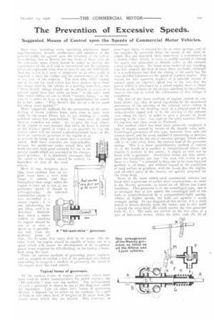
01 the various forms of engine governors which have been used by motor manufacturers for petrol engines, the " hit-and-miss " type was the earliest. The arrangement of such a governor is shown in one of the diagrams which we reproduce. Like ell other later forms of governing devices, it depends for its action on the tendency for a pair of balls or any other form of weights to fly away from the centre about which they are rotated. This tendency, or centrifugal force, is resisted by one or mure springs, and, as the weights fly outwards from the centre of the shaft on which they are mounted, their movement is transmitted to ii sliding collar, which, in turn, is readily caused to control the spark, the admission or throttle valve, or the exhaust valves of the engine. We know of no maker of any standing who has adopted the first of these three methods, although it is a well-known fact that the timing of the spark has the most decided influence on the speed of a petrol engine. The reason for this apparent neglect of a possible means of control upon an engine's speed lies in the fact that the power which is developed by a petrol engine bears a closer relation to the volume of the charge admitted to the cylindel than to the rate at which the combustion of that charge is completed.
The last of the three methods of engine control as outlined above, viz., that of speed regulation by the occasional prevention of the opening of the exhaust valve—which is accomplished by the drawing away of a hinged part of the exhaust-valve tappet rod, or by the moving of the exhaust cam along its shaft, in order to give a greater or lesser opening to the valvewas used on the early German Daimler engines, and those made by Panhard.
The method which has been most generally employed is that of engine control by means of the throttle valve only. Centrifugal governors of this type, however, have only one normal speed, and the usual method of increasing or decreasing this speed is by the aid of external springs, which either add to, or take away from, the normal load of the governor spring. This is a most unsatisfactory method of control as, in the hands of a careless or inexperienced driver, the engine is entirely at his mercy; it might as well not be fitted with a governor. Accelerator levers are very convenient for occasional use, but " the man who wants to get there in a hurry " is tempted to keep one in its most forward position at all times, and without regard to the conditions of road surface or gradient, with the result that the engine, and all other parts of the chassis, are quickly prepared for the scrap heap.
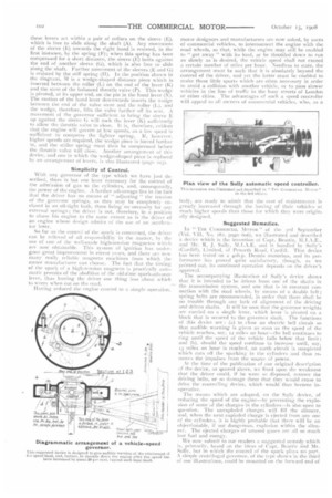
Some of the most widely-used commercial vehicles are rated with a governor of rather novel construction ; we refer to the Murray governor, as found on all Albion and Lacre machines. This governor is of the centrifugal type, and is so arranged that at low speeds the centrifugal pull of the balls is counterbalanced by a comparatively-light spring, whilst, at higher speeds, the balls act against a much stronger spring. In our diagram of this device, A is a shaft which is driven directly from the motor, and to this shaft is keyed the cross head (B) which carries the two governor balls (C, C. The balls are carried on the free ends of a pair of bell-crank levers, whilst the other ends (i), D) of these levers act within a pair of collars on the sleeve (E), which is free to slide along the shaft (A). Any movement of the sleeve (E) towards the right hand is resisted, in the first instance, by the spring (F); when this spring has been compressed for a short distance, the sleeve (E) butts against the end of another sleeve (G), which is also free to slide along the shaft. Further movement of the sleeves (E and () is resisted by the stiff spring (II). In the position shown in the diag-rant, M is a wedge-shaped distance piece which is inserted between the roller (L) on the end of the lever (K) and the stem of the balanced throttle valve (P). This wedge is pivoted, at its upper end, on the pin in the hand lever (N). The motion of the hand lever downwards inserts the wedge between the end of the valve stern and the roller (L), and the wedge, therefore, lifts the valve further off its seat. A movement of the governor sufficient to bring the sleeve E up against the sleeve G will rock the lever (K) sufficiently to allow the throttle valve to close. It is, therefore, evident that the engine will govern at low speeds, as a low speed is esufficient to compress the ligihter spring. If, however, higher speeds are required, the wedge piece is forced further in, and the stiffer spring must then be compressed before the throttle valve will close. Another arrangement of this device, and one in which the wedge-shaped piece is replaced
by an arrangement of levers. ilso illustrated (page 1031.
Simplicity of Control.
With any governor of the type which we have just described, there is but one lever necessary for the control of the admission of gas to the cylinders, and, consequently, the power of the engine. A further advantage lies in the fact that the driver has no means of " adjusting " the tension of the governor springs, as they may be completely enclosed in an oil-tight bath, there being no necessity for any external springs; the driver is not, therefore, in a position to abuse his engine to the same extent as is the driver of an engine whose design admits of the use of an accelerator lever, So far as the control of the spark is concerned, the driver can be relieved of all responsibility in the matter, by the use of one of the well-made high-tension magnetos which are now obtainable. This system of ignition has undergone great improvement in recent years, and there are new many really reliable magneto machines from which the motor manufacturer can choose. The fact that the timing of the spark of a high-tension magneto is practically automatic permits of the abolition of the old-time spark-advance lever, thus leaving the driver one thing less about which to worry when out on the road.
Having reduced the engine control to a simple operation,
motor designers and manufacturers are now asked, by users of commercial vehicles, to interconnect the engine with the road wheels, so that, while the engine may still be enabled to " get away " with its load, or be throttled down to run as slowly as is desired, the vehicle speed shall not exceed a certain number of miles per hour. Needless to state, the arrangement must be such that it is absolutely beyond the control of the driver, and yet the latter must be enabled to make those little spurts which are often necessary in order to avoid a collision with another vehicle, or to pass slower vehicles in the line of traffic in the busy streets of London or other cities. The advantages of such a speed controller will appeal to all owners of commercial vehicles, who, as a Thj invention was illustrated and described in 'Tire COMMERC IA I. MOTOR " on the 3rd
body, are ready to admit that the cost of maintenance is greatly increased through the forcing of their vehicles at much higher speeds than those for which they were originally designed.
Suggested Remedies.
In " TI1F. COMMERCIAL MOTOR " Of the rd September (Vol. VII, No. 182, page 6o6), we illustrated and described a device which is the invention of Capt. Beattie, NLI.A.E., and Mr. R. J. Sully, M.I.A.E, and is handled by Sully's (Cardiff), Limited, of Penarth Road, Cardiff. That device has been tested on a 4oh.p. Dennis motorbus, and its performance has proved quite satisfactory, though, as we pointed out, its continued operation depends cm the driver's approval.
The accompanying illustration of Sully's device shows that it is intended to be driven from one of the shafts in the transmission system, and one that is in constant connection with the road wheels, by means of a double belt ; spring belts are recommended, in order that there shall be no trouble through any lack of alignment of the driving and driven shafts. It will be seen that the governor weights are carried on a single lever, which lever is pivoted on a block that is secured to the governor shaft. The functions of this device are (a) to close an electric bell circuit so that audible warning is given as soon as the speed of the vehicle reaches, say, iz miles an hour—the hell continues to ring until the speed of the vehicle falls below that limit; and (b), should the speed continue to increase until, say, 13 miles an hour is reached, an earth circuit is completed which cuts off the sparking in the cylinders and thus removes the impulses from the source of power.
At the time of the publication of our original description of the device, as quoted above, we fixed upon the weakness that the driver could, if he were so disposed, remove the driving belts, or so damage them that they would cease to drive the controlling device, which would thus become inoperative. The means which are adopted, on the Sully device, of reducing the speed of the engine—by preventing the explosion of some of the charges in the cylinders—is also open to question. The unexploded charges will fill the silencer, and, when the next exploded charge is ejected from any one of the cylinders, it is highly probable that there will be an objectionable, if not dangerous, explosion within the silencer. The ejected charges of unused gases are all so much lost fuel and energy. We now submit to our readers a suggested remedy which is, primarily, based on the ideas of Capt. Beattie and Mr. Sully, but in which the control of the spark plays no part. A simple centrifugal governor, of the type shown in the third of our illustrations, could be mounted on the forward end of
the propeller shaft, or any other shaft whose speed of rotation bears a constant relation to that of the driving wheels, and it could be made to act as follows ;—(a) complete an electric bell circuit and give audible warning when the vehicle attains a speed equal to, say, 12 miles an hour; and (b), when the speed rose to 14 or 15 miles an hour promptly cause the wedge piece (or its equivalent) to be withdrawn from the Murray-type of governor, and thus cut off the source of power. The engine governor, as distinct from the vehiclespeed governor, should be set for a speed of about in or 13 per cent. higher than the maximum which is allowed for the vehicle when the latter is being driven on top gear; this provision will ensure that, right up to the moment previous to the vehicle-speed governor's coming into action, the engine will be receiving a " full bore " of gas for each cylinder.
The containing drum (a) is bolted on to a flange, or is otherwise fixed to the tailshaft of the gearbox, and inside this drum the levers (c, c), which carry the governor weights it), are pivoted at the points (d, d). Until the s{tted of the vehicle reaches 12 miles an hour, the free ends ef the levers (c, and their weights (b, b) are held in towards the centre of the drum by means of the helical springs cc, e); but, when that speed is reached, the weights fly outwards, by reason of the centrifugal force, and their movement causes the sleeve g to be rotated on the central extension of the drum, by means of the links f, f. Two studs (ho ill are screwed into the sleeve g, and these studs extend outwards rod engage in holes in the bridle sleeve j; the two sleeves ;alci i) must, therefore, rotate together, but, in addition to its angular motien, the bridle sleeve is caused to slide alongthe central extension of the drum by reason of the engagement of the pin 1 in a spiral slot (k), which -lot is Cut in the drum extension.
bridle (el) is !heed between the flanges of the sleeve (/), and a lever (n) is connected to this bridle, so that the sliding motion of the sleeve (j) may be employed for the purpose of ;
(I), moving a copper contact button into elect I
r.ca. commeCon with an insulated strip to which one terminal of the electricbell battery is atlachod; and (2), closing the throttle valve of the engine by means of a rod which extends from the vod of ifw Irver Although we have mentioned speeds of 12 and ts miles an hour as being the speeds for which this device should be adjusted, it must clearly be undersuxxl that, by the use of suitably-selected springs (e, e), the device could be arranged to perform its functions for any two speeds. We have taken 12 and 13 miles as probably suitable speeds to which the governor should be adjusted if it were to be fitted on a London motorbus. We do not suggest that this arrangement is the best that can be produced, but we are of opinion that it might form a useful basis for experiments from which practical results may follow.
The controller which we have outlined above would not, of course, prevent a driver from racing his engine during such times as when the gear is in its neutral position, or when driving the vehicle on its lowest gear, hut we are of opinion that such engine racing can more easily be checked, end is less damaging on the life of the machine, than the more serious racing of the vehicle over very rough road surfaces. The raring of an engine during the periods of traffic stops, or short halts for the delivery of goods, can only with certainly he avoided if an efficient self-starling gear is fitted 10 the engine; the temptation to " let her go " rather than lo run the risk of stopping the engine due to throttling down too much, is then removed, and the driver, thus released of all anxiety on that point, can give his attention to other, aed, perhaps, more important matters.