


Group Casting of Small Components
Page 48
If you've noticed an error in this article please click here to report it so we can fix it.
ACASTING process for the rapid production of small parts is shown in patent No. 579,097, by the Ford Motor Co. Ltd., 88, Regent Street, London, W.I. To ensure clean and dense castings, the centrifugal principle is used.
The drawing shows a specimen component (I) and the moulds used in making it. Six moulds (2) are formed in discs of suitable material, and they are then assembled vertically in pairs to any desired height, inside a barrel capable of being rotated.
The barrel is then set in motion, and the metal poured into a central runner (3). This leads to the bottom of the pile, from which point, six risers (4) communicate with the individual moulds. The pouring of the metal from the bottom is said to ensure that all the moulds are filled with liquid metal. The castings produced by this method are claimed to be. in many cases, superior to forgings.
ENGINE A BRAKE THROIUGH A TORQUE-CONVERTER WITH hydraulic transmission, the 11' engine has little or no effect as a brake during overrunning, and a device to make braking possible forms the subject of patent No. 579,692, which comes from W. Owen and Crossley Motors, Ltd. both of Gorton Lane, Manchester, 18.
The desired end is reached by incorporating in the torque converter a oneway clutch which is free during normal running, but locks on the overdrive. The clutch is torque-operated, and consists of two members built into the output shaft of the hydraulic coupling.
Referring to the drawing, one member is the backplate of a brake-like assembly and carries a pair of abutments (1). The second member consists of another plate carrying the pivot pins (2) of the shoe system.
When driving normally, the torque is transmitted from the pivot-pin blocks (3) to the abutments, and no action occurs. During overdriving, the torque direction is reversed, and the abutments then press on the free ends of the shoes and expand them into the outer drum.
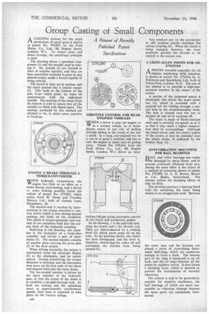
The last-named member is driven by the input member of the hydraulic gear, so that the action of the shoes is to establish a straight-through lock. As both the locking and the unlocking occur at approximately synchronous speeds, little wear is expected to take place on the friction linings. THROTTLE CONTROL FOR REAR. ENGINED VEHICLES WHEN a driver is near the engine, as VV in a normal vehicle, he is immediately aware of any risk of stalling through letting in the clutch at too low a speed. In a long, rear-engined bus he is not in so good a position, and has to race the engine to make sure of getting away. Patent No. 579,434, from the
Ford Motor td„ 88, Regent Street, London. Co.,W.1, shows an inter
locking linkage giving automatic control of the clutch and accelerator pedals.
In the drawing, 1 is the pull-rod operating the clutch and 2 the throttle rod. They are interconnected by a rocking lever (3), which meets stops (4) on the rods. In the position shown, the clutch has been disengaged, and the lever is,. therefore, obstructing the collar (6) and preventing the throttle from being opened far.
Any pressure put on the accelerator in this position merely stretches the spring coupling (5). When the clutch is being engaged, however, the lever gradually permits the throttle to be opened at the correct rate.
A LIGHT-ALLOY PISTON FOR OIL ENGINES
APISTON intended especially for oil engines employing solid injection, is shown in patent No. 579,616, by A. Robinson and Specialloid, Ltd., both of Friern Park, London, N.12. The aim of the scheme is to provide a high-temperature member in the centre of the crown.
A section of the proposed piston is illustrated; this shows the insert member (1), which is provided with a screwed tail for bolting through a central hole in the aluminium-alloy body. The bolt is riveted over the nut to abolish all risk of its working off.
The insert is made of flame-resistant steel and is partially air-spaced as at 2, so that it may reach a higher temperature than its surroundings. Although the insert covers only the central region of the croWn,.it May be extended over the whole recess, as indicated by the broken lines (3).
ANTI-VIBRATION MOUNTING FOR BALL BEARINGS
DALE_ and roller bearings can easily Elbe damaged by sharp blows, and to prevent continued vibration from producing the same effect is the object of a method of mounting shown in patent No. 578,989, by A. G. Brown, Boveri et Cie., Baden, Switzerland. The scheme utilizes the damping effects of thin oil films.
. The drawing portrays a bearing fitted with the mounting, the latter being shown at an exaggerated scale. Between the• outer race and the housing are placed a series of close-fitting sheetmetal half-rings, which are numerous enough to form a bush. The bottom part of the rings is immersed in an oil bath, and the oil seeps between all the pieces by capillary action. It thus forms a damping layer, which is claimed to prevent the transmission of harmful vibrations.
The scheme is said to be particularly suitable for stand-by machinery, the ball bearings of which are more susceptible to vibration damage because the same spots are continually hammered.