The Guy-Cotal Preselective Gear
Page 54

Page 55

If you've noticed an error in this article please click here to report it so we can fix it.
Electro-magnetic Epicyclic Four-speed Gearbox and Ingenious Fool-proof Preselective Change Mechanism. Magnetic Reverse and Eight
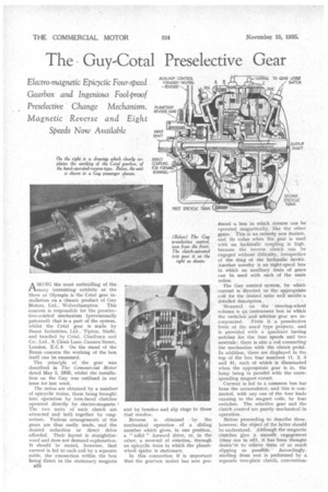
Speeds Now Available INPUT AMONG the most enthralling of the many interesting exhibits at the Show at Olympia is the Cotal gear installation on a chassis product of Guy Motors, Ltd.; Wolverhampton: This concern is responsible for the preseiective-controlmechanism (provisionally patented) that is a part of the system, whilst the Cotal gear is made by Beans Industries, Ltd., Tipton, Staffs, and handled by Cotal, Chadburn and Co., Ltd., 9, Cloak Lane, Cannon Street, London, E.C.4. On the stand of the Beans concern the working of the box itself can be examined.
The orincl.ple of the gear was described in The Commercial Motor dated May 3, 1935, whilst the installation on the Guy was outlined in our issue for last week.
The ratios are obtained by a numberi of epicyclic trains, these being brought into operation by iron-faced clutches operated directly by electro-magnets. The two units of each clutch are attracted and held together by magnetism. Various arrangements of the gears are thus easily made, and the desired reduction or direct drive afforded. Their layout is straightforward and does not demand explanation. It should be stated, however, that current is fed to each coil by a separate cable, the connection within the box being direct to the stationary magnets u28 and by brushes and slip rings to those that revolve.
Reverse is obtained by the mechanical operation of a sliding member which gives, in one position, a " solid " forward drive, or, in the other, a reversal of rotation, through an epicyclic train in which the planetwheel spider is stationary.
In this connection it is important that the gearbox maker has now pro
aimed a box in which reverse can be operated magnetically, like the other gears.. This is an entirely new feature, and its value when the gear is used with an hydraulic coupling is high, because the reverse clutch can be engaged without difficulty; irrespective of the drag of the hydraulic device. Another novelty is an eight-speed box in which an auxiliary train of gears can be used with each of the main ratios.
The Guy control system, by which current is directed to the appropriate coil for the desired ratio well merits a detailed description.
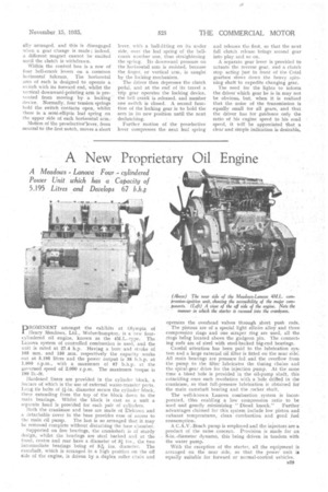
Mounted on the steering-wheel column is an instrument -box in which the switches. and Selector gear are in corporated. FrOril it a preselective lever of the usual type projects, and is provided with a quadrant having notches for the four speeds and two neutrals ; there is also a rod connecting the mechanism with the clutch pedal. In addition, there are displayed in the top of the box four numbers (1, 2, 3 and 4), each of which is illuminated when the appropriate gear is in, the lamp being in parallel with the corresponding magnet circuit.
Current is fed to a common bus bar from the accumulator, and this is conirected, with any one of the four leads running to the magnet coils, by four switches. The selective gear and the clutch control arc purely mechanical in operation.
Before proceeding to describe these, however, the object of the latter should be understood. Although the magnetic clutches give a smooth engagement (they run in -oil), it has been thought desira',Ie to relieve them of as much slipping as possible. Accordingly, starting from rest is performed by a separate two-plate clutch, convention ally arranged, and this is disengaged when a gear change is made ; indeed, a different magnet cannot be excited until the clutch is withdrawn.
Within the control box is a row of four bell-crank levers on a common horizontal fulcrum. The horizontal arm of each is designed to operate a • s,.•.'itch with its forward end, whilst the vertical downward-pointing a,rm is prevented from moving by a locking. device. Normally, four tension springs hold the switch contacts open, whilst there is a semi-elliptic leaf spring on the upper side of each horizontal arm.
Motion of the preseleetivelever, from neutral to the first notch, moves a short lever, with a ball-fitting on its under side, over the leaf spring of the bellcrank number one, thus straightening the spring. Its downward pressure on the horizontal arm is resisted, because the finger, or vertical arm, is caught by the locking mechanism.
The driver then depresses the clutch pedal. and at the end of its travel a trip gear operates the locking device, the bell crank is released, and number one switch is closed. A second function of the locking gear is to hold the arm in its new position until the next declutching.
Further motion of the preselective lever compresses the next leaf spring and releases the first, so that the next full clutch release brings second gear into play and so on.
A separate gear lever is provided to actuate the reverse gear, and a clutch stop acting just in front of the Cotal gearbox slows down the heavy spinning shaft to expedite changing gear.
The need for the lights to inform the driver which gear he is in may not be obvious, but, when it is realized that the noise of the transmission is equally small for all gears, and that the driver has for guidance only the ratio of his engine speed to his road speed, it will be appreciated that a clear and simple indication is desirable.


