


Mechanical Horse-Power:
Page 24
If you've noticed an error in this article please click here to report it so we can fix it.
What It Is, and How It Is Measured. (Continued from page 202 .
Brake Horse-power.
The usual method of ascertaining the horse-power of a motor engine is to actually measure it at the fly-wheel by means of suitable apparatus. Thus brake horse-power (B.H.P.) is that which the motor is able to transmit to the after member of the clutch (not to the wheels, for there are several other resistances interposed), and it is, therefore, less than the indicated horse-power of the motor. Brake horsepower is so called because the apparatus used in measuring it usually takes the form of a brake on the fly-wheel, though the brake may be any one of several types. If, when a fly-wheel is revolving, we take a handspike or a long piece of wood and, placing one end on the floor under the wheel, pull up on the other, bringing pressure to bear on the fly-wheel, we can prevent the motor racing, or even bring it to a stop. If we could measure the strength of our pull we should be able to arrive at the power of the motor. That in principle is how the brake horse-power is obtained. The earlier arrangement adopted with this object was called the " prony " brake. It took several forms, but perhaps the most common was as illustrated.
This arrangement consists of two wooden blocks with V cuts, which are bolted round the shaft (not the fly-wheel in this case). Attached to the upper block is a long arm graduated in feet and inches, and to this is attached a weight. The tension on the bolts and the position of the weights are then so regulated as to maintain the brake in equilibrium. The power developed by the engine was represented by a formula employing the weight, its distance from the centre of the shaft, and the speed of revolution. This method, however, was too jerky and unsatisfactory.
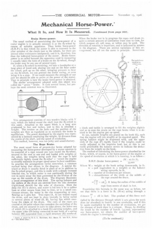
The Rope Brake.
The most usual form of present-day brake adopted for measuring the horse-power developed by a motor consists in its essential of a rope wound one turn round the fly-wheel, secured to the roof at one end and loaded with weights at the other, the weights being such that the rope is held sufficiently tightly round the fly-whee '7Nermit the engine to steadily maintain its proper speed unuer its best conditions. In practice the arrangement varies somewhat, a common method being that shown in the diagram. A special flywheel or drum is usually fitted in place of or in addition to the fly-wheel proper, and this is made with a deeply recessed internal rim, in which water is run continually during the test to carry away the heat generated by the friction of the rope on the outside of the drum. The diagram illustrates a usual arrangement of this kind. The spring balance and the spokes of the drum are omitted from the side elevation (right-hand sketch) for the sake of clearness. Here the deep rim (C) is shown, and water is led into it by a rubber hose or other means from time to time, or in a small continuous stream, the water in the rim evaporating or overflowing as it gets hot. Two ropes (A, A) are wound round the drum, and are kept in place laterally by being nailed to several pieces of wood (B, 13). having lips which overhang the edges of the drum. The ends of the ropes are crossed at the point where they complete the encircling of the drum, and are secured in pairs to yoke pieces, the lower one of which (E) is attached to a hook (G) carrying weights, and 1 he upper yoke (D) being connected to one hook of a spring balance (H) suspended from a rigid structure (K) overhead.
* From a paper hv R. G. L. Markham, ILI, Mech. E. late R.N., F.ditor "The Motor Boat,"
When the brake test is in progress the ropes and drum require a certain amount of lubrication from time to time, for which purpose oil, soft soap, or tallow may be used. The direction of rotation is important, and is indicated by arrows in the diagram. There are several variations of this arrangement, but all are the same in principle. Sometimes
a block and tackle is arranged to lift the weights slightly and so to ease the strain on the rope brake when it is desired to let the engine get up speed.
In use, suitable weights are placed on the hook (G), such that the engine will run steadily at its required speed. The spring balance might be dispensed with, and the upper ends of the rope (F) rigidly fixed if the weights could be easily adjusted to the requisite load, but as this is not easily practicable the balance serves to indicate the deduction from the weight on the hook.
The method of calculating the horse-power absorbed by the brake, which, of course, is the horse-power of the engine at the speed of revolution at which it is running, is as follows : Examining this formula in the same way as before, we see that there is a force in lb. (W-w) acting through a distance x 2R in feet. The product of this force mill
tiplied by the distance through which it acts gives the work done (or absorbed) in foot-lb. in one revolution, and if this be again multiplied by the number of revolutions, we get the amount of work done in a minute, Hence, by dividing the result by the number of foot-lb. (33,000), representing one horse-power, we obtain the number of horce-power which the engine is developing.