


An Hydraulic Brake Regulator
Page 68
If you've noticed an error in this article please click here to report it so we can fix it.
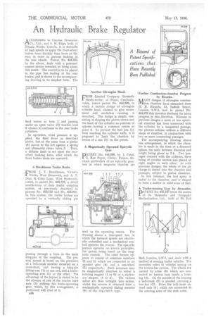
ACCORDING to Clayton Dewandre Co., Ltd., and S. H. Edge, both of Titanic Works, Lincoln, it is desirable at high speeds to apply the front-wheel brakes more forcibly than those at the rear, in order to prevent locking of the rear wheels. Patent No. 444,955 by the above, deals with a pressurecontrol device intended to bring about this result. The control is to be placed in the pipe line leading to the rear brakes, and is shown in the accompanying drawing in its simplest form. The
fluid enters at boss 1 and passing • under an open valve (3) reaches boss 2 whence it continues to the rear brake cylinders.
In operation, when pressure is applied, the fluid flows as described above, but at the same time a piston (4) moves to the left against a spring and ultimately closes valve 3. Thus, a definite limit is set upon the rearwheel braking force, after which the front brakes alone are operated.
A Brockhouse Trailer Brake. FROM J. T. Brockhouse, VictoriaWorks, West Bromwich, and A. T.
Dear, 6, Coles Lane, West Bromwich, comes, in patent No. 445,128, a detail modification of their trailer coupling system, as previously described in patents No. 422,122 and No. 435,94z1. In this system, the trailer brakes are operated by a vertically sliding pin passing through a• bore in the main king-pin of the coupling. The present patent is based on the provision of a bell-crank member mounted on a cross-shaft, and having a king-pin lifting arm (1) at one end, and a brakeoperating arm (2) at the other. The advantage of the layout is stated to be the absence of risk of the tractor back axle (3) striking the brake-operating gear, which, by this arrangement, is positioned well clear of it.
ri50 Another Oil-engine Head.
rROM Limited Company (formerly
Skoda-werke) of Plzen, Czechoslovakia, comes patent No. 444,806, in which a further design of oil-engine cylinder head, claimed to give economical and smokeless running, is described. The design is simple, consisting of shaping the piston crown and the head of the cylinder as portions of spheres having a common centre at point 2. To prevent the fuel jets (1) from reaching the cylinder walls, it it proposed to limit the chamber by means of a rim (3) on the piston.
used as the operating means. The drawing shows a four-speed box in which the forward speeds are electrically controlled and a mechanical control operates the reverse. The epicyclic portion operates on known principles, the patent being based on the mag
netic control. The chief feature appears to consist of armature members (2 and 5) which are connected to an annular gear (8) and a sun-wheel (7) respectively. Each armature may be magnetically clutched to either a rotating magnet (1 or 6) or a station
ary magnet (3 or 4). The various ratios are thus brought into action, whilst the reverse is obtained from a mechanically operated sliding member (9) of the dog-clutch type. Further Combustion-chamber Progress by Ricardo.
ft /I ANY designs of oil-engine comboslifition chamber have emanated from H. R. Ricardo, 21, Suffolk Street, London, S.W.1, and in patent No. 444,879 this inventor discloses the latest progress in this direction. Whereas in previous designs a more or less spherical chamber has been connected with the cylinder by a tangential passage, the present scheme utilizes a different shape of chamber, in conjunction with two or more connecting passages.
The accompanying drawing shows one arrangement, in which the chamber is made in the form of a flattened sphere, the ratio between diameter and height being given as 7:4. Two passages connect with the cylinder, these being of circular section and placed at right angles to each other. As with previous designs, the whole of the air charge is forced into the chamber and passages, subject to piston clearance.
. In this instance, the fuel spray is radial to the chamber, and is shaped to form a hollow or solid cone of fuel.
A Trailer-steering Gear by Straussler.
PATENT No. 445,165 bears the names of N. Straussler and Straussler Mechanization Ltd., both of 70, Pall
Ma 1, London, S.W.1, and deals with a method of steering trailer vehicles. The invention refers to vehicles sprung on the torsion-bar system. The wheels are carried by arms (5) which are connected to torsion bars inside a housing (4). On the outside of the housing a bell-crank (2) is pivoted, carrying a tow-bar (3). From the bell-crank extend rods (1) which are connected to the steering arms of the stub axles.