


Sunbeam Introduces A MODIFIED TROLLEY-BUS Chassis
Page 48
Page 49
If you've noticed an error in this article please click here to report it so we can fix it.
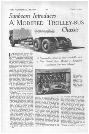
A Regenerative Motor is Now Available with. a New Control Gear, Whilst a Simplified Transmission has been Adopted IT is rather more than two years since the Sunbeam Motor Car Co., Ltd., Moorfield Works, Wolverhampton, first entered the commercial-motor field with a six-wheeled petrol-engined vehicle ; nearly a year ago we announced that, in addition, a six-wheeled trolleybus was being introduced. A vehicle of this type has since then been in constant service on an arduous route in Wolverhampton, and has given great satisfaction.
A further order for a modified type of vehicle has just been placed with the Sunbeam concern by the Wolverhamp
ton municipality. Broadly speaking, the main alteration concerns the power unit which, on the machines in question, is of the regenerative type, an interesting feature being that the minimum road speed when regeneration takes place has been reduced to 8 m.p.h. This new vehicle, known as the M.S.2 type, does not displace the M.S.1, but It is an additional model.
Besides the introduction of the regenerative motor, several other chassis details have been improved. The transmission, the control, and the method of wiring are the principal items calling for comment.
With a wheelbase of 17 ft. (measured from the front axle to the centre of
the bogie) and a track of 6 ft. ins. (front) and 6 ft. 21 ins. (rear), the chassis is intended as the basis of the largest type of double-deck coachwork.
The after portion of the frame (behind the third axle) has been swept down to provide a platform height (laden) of but 1 ft., whilst the main Part of the frame is 2 ft. 1 in. high. The complete weight of the chassis is 4 tons 8 cwt. 1 qr., and, despite an overall length of 27 ft. 5i. ins., a tuIning circle of under 60 ft. is provided.
The motor, designed and manufactured by Metropolitan Tickers, Ltd., is mounted amidships in the chassis on a rigid sub-frame and is rated at 70 h.p. with 500 volts d.c. It is of the compound-wound type and allowance has been made for heavy overloads.
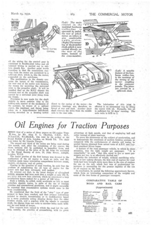
The main interest in this new trolleybus chassis concerns the controller, which is of a new type produced jointly by the B.T.H. and Metropolitan ViAers concerns. An accelerator pedal of the plate type is mounted in such a position that it is conveniently placed for operation by the driver's right foot. Through a system of links, a scissortype main controller is operated, the contacts being arranged so that the accelerative powers of the vehicle are definitely proportional to the amount that the pedal is depressed.
The controller switch is interlocked with a reverse, neutral and forward switch fitted on the dash-board and operable by the driver's left hand, and it ensures that the pedal is in the " off " position before the driver can alter the directional switch. The scissor-type pedal-operated controller switch does not carry the main current ; the contactors operate solenoids on the main contactor panel.
The shunt-contactor panel is the first of a new type and is carried on the
near side of the front panel of the cab. Each contactor has a suitable resistance, wired in series, which obviates arcing on the contact& Furthermore, a coil is used to eut out the line circuit when a pole leaves the overhead wire and the vehicle is in motion, thereby preventing a barn-out of the lamps— as the motor is of the regenerative type, this would otherwise be possible. The circuit is brought . back to normal by pressing a button mounted in an accessible position on the front dash panel.
Resistances are mounted on each side of the main frame, the series component being on the near side and the shunt on the off side. Care has been taken to ensure that the heated elements are properly ventilated and shielded from the lower saloon. The resistances are wirebound, rustless, jointless and are claimed to be unbreakable.
It might be mentioned in passing that
MI the wiring for the control gear is contained in flexible-steel tubes and all internal wiring is carried out in cabtyre sheath flex. Another point worth recording is that tfie connections running from the motor are contained in a split-oak cleat, which is, like the motor; suspended on the sub-frame.
The modification in the chassis concerns the layout of the transmission, the rear end of the motor now forming the means for mounting the universal joint to the propeller shaft. It will be recalled that on the M.S.1 chassis the forward end of the propeller shaft was carried by a universal joint slung from the frame.
Provision is now made for the shaft slightly to move endwise (due to the leading-axle control of the mechanics of the system), by means of a splined sleeve, the resultant end thrust being taken on a large-diameter ball-thrust bearing mounted in a housing bolted direct to the casing of the motor ; the armature bearings are, therefore, relieved of any end load. Another short shaft conveys the drive from the middle axle to the rear axle.
• The lubrication of this joint is effected in an economical way by filling the centre with oil. Normally, this oil is sufficient for 10 days' running. The axle ratio is 0.75 to 1.