


Constant-speed Drive
Page 80
If you've noticed an error in this article please click here to report it so we can fix it.
THE object of a control mechanism shown in patent No. 833,273 is to avoid driving engine auxiliaries at an unnecessarily high speed. (Ford Motor Co., Ltd., 88 Regent Street, London, W.I.)
The drawing shows the components in a diagrammatic assembly. The engine drives the outer annulus of an epicyclic unit (1) at a widely varying speed. The output member is a pulley (2) connected to a smaller sunwhcel (3). • This pulley drives an oil pump (4), which can also be used to power hydraulic auxiliaries.
Constant speed from a varying input is obtained by allowing the epicyclic unit to lose speed in ratio to the power required to drive another oil pump. A secondary sunwheel (5) is attached to a pulley (6) which drives the other pump (7).
The two oil pumps are connected by spring-loaded valves (not shown). If the speeds tend to increase, the valves, by throttling the flow, impose more load on the upper pump. This slows it down, reducing the speed of the secondary sunwheel and planets, which lowers the speed of the epicyclic unit. The patent describes in detail the various units employed in the system.
RELAY-OPERATED STEERING
POWER-ASSIS1ED steering mechanisms normally employ column movement to operate the servo control valve. Patent No. 833,778 describes a layout in which a pressure-operated relay is interposed between the column and
valve. (Reg ie Nationale des Usines Renault, 8-10 Avenue Emile Zola, Billancourt, Seine, France.) Referring to the drawing, the steering column transmits its torque to the worm through a helically splined joint (1). At the bottom of the column is a disc (2) which moves when the column is turned until arrested by abutments. The abutments are actually valve faces through which the,oil is circulated by a pump. Parallel . with this circuit is a servo cylinder (3) which powers the steering.
When the column is turned, the disc obstructs one of the valve faces and gives extra clearance to the other. The pressure difference so created is applied, through a cross-over (4), to the spaces (5 and 6) on each side of the bobbin valve (7).
The bobbin controls the main oil supply to the servo, energizing one side and venting the other. The back-pressure created on the disc provides the driver with a slight but proportional reactive resistance. If power fails the disc transmits the column torque direct to the worm, once the slack has been taken up.
PREVENTING BRAKE SQUEAL THE bell-like shape of a brake drum makes it prone to squeal if resonance is created. Patent No. 833,643 describes a damping device to prevent this effect.
(The Motor Industry Research Association, Lindley, Nuneaton.)
The principle is to hold a rubbing surface firmly in contact with the edge of the drum. Referring to the drawing, the drum (1) is provided with four metal segments (2). These are pressed against the edge of the drum by a number of sheet-metal clips (3).
Alternatively, frictionfaced segments may be used with, instead of spring clips, spring-loaded screws passing through clearance holes in the segments. The device is claimed to damp out tangential and radial vibrations.
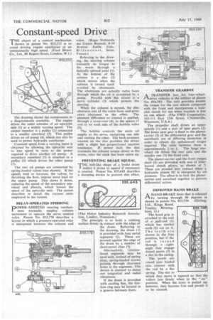
H the drum is provided with cooling fins, the friction ring may be located in a groove between them. • TAANSFER GEARBOX
In.A TRANSFER box for four-wheeldrive vehicles is the subject of patent No. 834,583. The unit provides double the torque for the rear wheels compared with the front and incorporates a lockable clutch for use when traction is lost on one wheel. (The FWD Corporation, 105-111 East 12th Street, Clintonville, Wisconsin, U.S.A.) The propeller shaft drives an upper spindle (1) and a pair of spur gears (2). The lower spur gear is fixed to the planetcarrier (3) of the differential gear and the sunwheels are of differing diameters in order to obtain We unbalanced torque required. The ratio between them is approximately 2 to 1. The large sunwheel (4) drives the rear axle and the smaller one (5) the front axle.
The planet-carrier and the front output shaft (6) are provided with sets of interleaved clutch plates, as shown at 7. These are pressed into contact when a hydraulic piston (8) is energized by oil pressure. The effect is to lock the planetcarrier and sunwheel together to prevent differential action.
IMPROVED HAND BRAKE
A HAND-BRAKE lever that is released 1-1. by turning through 90 degrees is shown in patent No. 833,739. (Girling, Ltd., Kings Road,
. Tyseley, Birmingham, 11.) The hand grip is attached to the end of a pull-rod (1) which has ratchet teeth (2) cut on it. The teeth are shown in the free position, but if the rod is turned through a rightangle they engage detent pawls (3) in a slot in the casing.
The pawls are round pins loaded into contact with the rod by a flat spring. The slot in which they move is tapered so that the rollers jam firmly when in the "on" position. When the lever is pulled up, however, they become free and permit it to be rotated.