


A Magnetically Operated Gearbox
Page 60
If you've noticed an error in this article please click here to report it so we can fix it.
PATENT No. 729,831 comes from 1 S. A. Andre Citroen, 117-167 Quai de Javel, Paris, and gives details of a magnetically operated gearbox. The
chief feature is that slip rings or other current-carrying joints are not required.
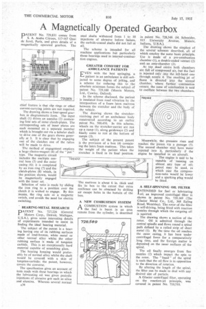
The drawing shows a four-speed gearbox in diagrammatic form. The input shaft (1) drives an annulus (2) containing four sets of outer clutch-plates. The corresponding sets of inner plates are each mounted on a separate member which is brought out via a tubular shaft to drive one of the gears shown generally at 3. It is clear that by engaging one of the clutches one of the ratios will be made to drive.
The method of engagement employs a lauge electro-magnet (4) of the " pot " type. The magnetic circuit includes the multiple central boss (5) and the outer casing (6); it is completed by an iron ring (7) and the clutch-plates (8) which, in the position shown, would be magnetically engaged with the inner set, ,
Selection of ratio is made by sliding the iron ring to a position over the clutch it is wished to engage. By this means, the ring acts as a magnetic switch and avoids the need for electric switching.
BEARING-METAL RESEARCH
PATENT No. 727,226 (General I Motors Corp., Detroit, Michigan, U.S.A.), gives some interesting details of experiments intended to assist in finding the ideal bearing material.
The subject of the patent is a bearing having one of its rubbing surfaces made of lead-bronze, white metal or other normal alloy whilst the other rubbing surface is made of tungsten carbide. This is an exceptionally hard material capable of scratching glass.
The bearing housing would preferably be of normal alloy whilst the shaft would be covered with a skin of tungsten-carbide; the patent, however, covers the converse.
The specification gives an account of tests made with these bearings in which the lubricating oil was given periodic injections of abrasive grit such as silica and alumina. Whereas several normal A34 steel shafts withstood from 1 to 10 injections of abrasive before failure, the carbide-coated shafts did not fail at all.
The scheme is intended for all machine applications but particularly those bearings used in internal-combustion engines.
GREATER COMFORT FOR AMBULANCE PATIENTS VEN with the best springing, a patient in an ambulance is still subjected to some degree of jolting, and a scheme for reducing this to the absolute minimum forms the subject of patent No. 729,100 (Morris Motors, Ltd., Cowley, Oxford).
In the scheme disclosed, the patient is insulated from road vibration by the interposition of a foam latex mattress between the stretcher and the body of the vehicle.
The drawing shows the stretcherreceiving part of an ambulance body constructed according to an earlier. patent No. 500,450. In this scheme, wheels on the • stretcher-carrier are run up a ramp (I), along guideways (2) and finally come to rest at the bottom of ramps (3).
The subject of the present patent is the provision of a box (4) containing the latex foam mattress. This takes the weight of the patient when the stretcher is fixed in its final position.
The mattress is about 6 in, thick and fits its box to the extent that extra resilience can be obtained by drilling air escape holes in the bottom of the box.
A NEW COMBUSTION SYSTEM A COMBUSTION system in which I-1 the fuel is burnt in art area remote from the cylinder, is described in patent No. 728,549. (H. Schneider, 915 University Avenue, Muncie, Indiana, U.S.A.).
The drawing shows the simplest of the several schemes described, all of which employ the same basic principle. Use is made of a pre-combustion chamber (1), a double-ended ventnri (2) and. an ante-chamber (3).
At top dead centre both chambers arc full of compressed air, but the fuel is injected only into the left-hand one through nozzle 4. The resulting jet of flame is directed into the second chamber, where further combustion occurs; the zone of combustion is said to oscillate between the two chambers.
Meanwhile, the pressure rises and reaches the piston via a passage (5). The second chamber may have water injected into it, particularly if the engine be installed in an aircraft.
The engine is said to be capable of running on almost any type of oil; petrol may be used, in which case the compression-ratio would be lower and a sparking plug would he fitted.
A SELF-SPINNING OIL FILTER INTENDED for fuel or lubricating I oil, an improved centrifugal -filter is shown in patent No. 729,169 (The Glacier Metal Co., Ltd., 368 Ealing Road, Wembley). The rotor of the filter is self-driving, being fitted with reaction nozzles through which the outgoing oil is squirted.
The drawing shows a section of the rotor. Oil is admitted through the central spindle and flows round a spiral path defined by a rolled strip of sheet metal (1). By the time the oil reaches the outer casing, it has been under centrifugal force for a comparatively long time, and the foreign matter is deposited on the inner surfaces of the spiral.
The oil finally emerges from fine nozzles (2) which impart the spin to the rotor. The " hapd " of the spiral is such that the oil flow is in opposition to the direction of rotation.
By altering the length of the spiral, the filter can be made to deal with any desired size of particle.
A Glacier centrifugal filter, operating on the reaction-jet principle, was covered in patent No. 710,510,