


MAKING BEST USE OF THE FORD.
Page 15
If you've noticed an error in this article please click here to report it so we can fix it.
Valuable A dvice on Every Phase of Ford Transport, Which Will Appeal to the Owner, Driver and Repairer.
IN THIS series of hints concerning the Ford light chassis and ton truck wherever they are employed for commercial purposes, we endeavour to deal with the subject from every view-point, so that the advice given will appeal to the owner, driver, maintenance engineer or mechanic.
We shall welcome for inclusion among the hints those which have proved of value to individual users, and will make suitable remuneration for any such information which we publish. Readers are recommended to obtain the original " Book of the Ford," which constitutes a complete manual dealing with the Ford car, the van and the truck. 2s. 9d. post free from the offices of this journal.
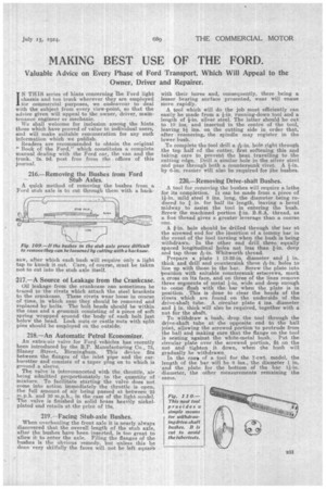
216.—Removing the Bushes from Ford Stub Axles.
A quick method of removing the bushes from, a Ford stub axle is to cut through them with a hack saw, after which each bush will require only a light tap to knock it out. Care, of course, must be taken pot to cut into the stub axle itself.
217.—A Source of Leakage from the Crankcase.
Oil leakage from the crankcase can sometimes be traced to the rivets which attach the steel brackets to the crankcase. These rivets wear loose in course of time, in which case they should be removed and replaced by bolts. The bolt heads should be within the case and a grurnmit consisting of a piece of soft spring wrapped around the body of each bolt just below the head. Lock nuts or castle nuts with split pins should he employed on the outside.
• 218.—An Automatic Petrol Economizer.
An extra-air valve for Ford vehicles has recently been introduced by the B.P. Manufacturing Co., 73, Slaney Street, Birmingham. This device fits between the flanges of the inlet pipe and the carburetter and consists of a taper plug on to which is ground a sleeve.
The valve is interconnected with the throttle, air being admitted proportionately to the quantity of mixture. To facilitate starting the valve does not come into action immediately the throttle is open, the full amount of air being passed at between 25 m.p.h. and 30 m.p.h., in the case of the light model. The valve is finished in solid brass heavily nickelplated and retails at the price of 15s.
219.—Facing Stub-axle Bushes.
When overhauling the front axle it is nearly always discovered that the overall length of the stub axle, after the bushes have been inserted, is too great to allow it to enter the axle. Filing the flanges of the bushes is the obvious remedy, but unless this be done very skilfully the faces will not be left square with their bores and, consequently, there being a lesser bearing surface presented, wear will ensue more rapidly.
A tool which will do the job most efficiently can easily be made from a 4-in, running-down tool and a length of i-in, silver steel. The latter should be cut to 10 ins, and inserted in the centre of the tool, leaving 5i ins, on the cutting side in order that, after reamering, the spindle may register in the lower bush.
To complete the tool drill a 2e-in. hole right through the top half of the cutter, first softening this and taking care to prevent the heat travelling to the cutting edge. Drill a similar hole in the silver steel and pass through both a countersunk rivet. A
by 6-in, reamer will also be required for the bushes.
220.—Removing Drive-shaft Bushes.
A tool for removing the bushes will require a lathe for its completion. It can be made from a piece of mild steel 8 ins. long, the diameter being re duced to in. for half its length, leaving a bevel midway to assist the tool in entering the hush.
Screw the machined portion B.S.A. thread, as a fine thread gives a greater leverage than a coarse one.
A i-in. hole should be drilled through the bar at the screwed end for the insertion of a tommy bar in the event of the tool turning when the bush is being withdrawn. In the other end drill three equally spaced longitudinal holes not less than Fin, deep and tap these Arin. Whitworth thread.
Prepare a plate 1 13-32-in, diameter and in. thick and drill and countersink three ek-in. holes to line up with those in the bar. Screw the plate into position with suitable countersunk setscrews, mark a cross on its face, and on three of the lines remove three segments of metal }-in. wide and deep enough to come flush with the bar when the plate is in position. This is done to clear the heads of the rivets which are found on the underside of the drive-shaft tube. A circular plate 4 ins, diameter and in. thick will also be required, together with a nut for the shaft.
To withdraw a bush, drop the tool through the drive-shaft tube atthe opposite end to the ball joint, allowing the screwed portion to protrude from the ball and making sure that the flange on the tool is seating against the white-metal bush. Put the circular plate over the screwed portion, fit on the nut and tighten it down, when the bush will gradually be withdrawn.
In the case of a tool for the 7-cwt. model, the length of the bar will be 8 ins., the diameter 1 in. .and the plate for the bottom of the bar 1i-in. diameter, the other measurements remaining the same.