


HYDRAULIC FRONT-WHEEL BRAKES.
Page 70
If you've noticed an error in this article please click here to report it so we can fix it.
A Resume of Recently Published Patent Specifications.
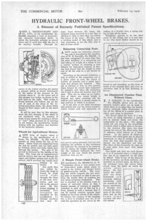
JMIN I. THORNYCROFI` AND CO., LTD., in its specification No. 263,969, describes a form of hydraulically operated front-wheel brake, in which the hydraulic cylinder is placed above and in axial line with the pin of the steering knuckle. Through the
centre of the hollow steering pin passes a plunger which is forced downwards by the action of the pressure in the cylinder above it. At the lower end of this plunger is a wedge, as shown in the half view on the right. This wedge is forced between two rollers, one on the end of each of the shoes of the internal-expanding brake, the shoes being hinged at their upper ends in the usual manner.
It will be seen that by this arrangement the free steering of the wheel is not interfered -with. No mention is made of any means for enabling a driver to " feel " what pressure he is exerting on his brakes, the specification merely dealing with the position and function of the hydraulic cylinder.
Wheels for Agricultural Motors.
ANEW form of tractor wheel is
shown in the specification of J. Dawe, No. 263,965. In this wheel a number of rings forms the rim of the wheel. These rings are supported from the hub by spokes, and are held apart by distance pieces and bolts which pass through the spokes. The grip of the ground is obtained by the waving of the rings. The rings are of comparatively narrow section and can cut through the upper and lighter ground and reach the subsoil, which prevents the vehicle from ,sinking in too deeply.
Any earth that may collect between the rings is forced by fresh earth right through the rings at the next revolution, and can fall on the ground again. By this means clogging is prevented, b u t scrapers are described in the
specification t o dislodge anything that may be
come fixed between the rings, the scrapers being mounted in a bar that is allowed to slide so that they can follow the waves of the rings. We have seen a working model of this wheel, and it was eurprising to see the firm grip it had of loose earth.
Balancing Connecting Rods.
A NEW means for balancing connect
ing rods is described in the specification of W. E. Ratcliffe, No. 264,005. It has been recognized for some time that the mere weighing of a connecting rod and taking its weight as a whole is not a correct method of ensuring a true balance for high-speed engines it baying been found that the weight at each end of all the rods in a set should be equal. According to the prerent invention, a hole is drilled in the connecting rod at a given point as near the centre of gravity as possible and a small hard ened and ground pin inserted. This pin is allowed to rest on two parallel edges formed by round bars supported by uprights, and when the connecting rod is laid in place the heavier part will sink. This can be taken as an indication of where any excess weight is located, and when corrected and the rods in even balance it should remain in any position in which it is placed.
It is not easy to see what advantage this system has over the Avery machine, which weighs each end separately on two special spring balances, and hot only indicates the position of any unbalance but indicates the amount to be removed, and by adding the weight registered on the two balances indicates the total weight of the rod, which the present invention does not do.
A Simple Front-wheel Brake.
IN specification No. 263,904 Dr. F. W.
Lanchester shows a very simple form of front-wheel brake which might be useful in the lighter and cheaper forms of goods-carrying vehicle. The coupling bar which connects the two steering arms is mounted so that it can perform the double duty of coupling bar and brake-actuating mechanism. This bar is attached to its steering arms by means of universal joints, so that a limited amount of rotation is possible. Attached to each end of this rod is a lever, jointed in such a manner that it can by partial rotation operate band brakes on the front wheels of the vehicle. To actuate the rotation of the coupling bar, a lever is attached near one of Its ends for operation by the driver by the
pulling of a flexible wire, a spring acting to take off the brake.
Simplicity appears to be the chief point of the design, but it is not easy to see why band brakes should be re forced to and described, as this form of brake is not popular here, and even on American cars it is fast declining in favour.
An Illuminated Number Plate Without Glass.
FG. GALLEY, in his specification
• No. 263,562, shows how an illuminated number plate can be made in which there is no glass that can become broken, although, when illuminated, it has all the effects of a number plate in which opal glass is employed.
The device takes the form of a box, the front of which resembles a stencil and is painted black and forms the background of the plate. The spaces which are cut away in the stencil-like structure allow a white plate to be seen. In the daytime this plate lies close against the stencil, the effect being that of ordinary white letters on a black
ground. In the period of darkness, however, this white plate can be slanted backwards so that it catches the light from the bulb that supplies the illuminant for the regulation red light. The effect of this is exactly the same as if opal glass were used with lights behind it.
One might ask, how are such figures as 0 or S produced where a black portion has to be supported on all sides by white? This is one of the features of the invention, as these portions are mounted on curved arms, a.s shown in the left-hand view, the curves being struck from the point on which the white plate hinges. By this means the white plate can hinge backwards and forwards without interfering with the centres of the figures mentioned. A Bowden wire controls the movement of the white plate and at the same time operates the electric switch.