


Coach Body with Two-level Seating
Page 66
If you've noticed an error in this article please click here to report it so we can fix it.
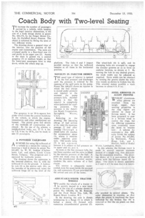
TO increase the number of passengers carried by a vehicle, while keeping to the legal exterior dimensions, is the aim of a body design shown in patent No. 642,172, by the Fa!gar Motor Co., Ltd., 24, Guildhall Street, Preston. The object is achieved by fitting the seats at Iwo different levels.
The drawing shows a general view of the interior, also the position of the engine and transmission. The seats are arranged partly in a floor-level row (1) and partly in an upper row (2). Access to the seats is gained via a central gangway (3) at medium height, so that the lower-seat passengers have to step down, whilst the others step up.
The gangway is an 18-in.-square box girder which forms the central backbone of the vehicle, in which the engine, transmission and other mechanisms are housed. The patent gives full details of the methods of construction employed. By the use of the scheme, a standard-sized body, say, 27 ft. 6 ins. by 7 ft. 6 ins. by 10 ft., can be made to seat 52 passengers.
A POWERED TAILBOARD
ASCHEME for using the tailboard of a vehicle as a means for raising or lowering a load is shown in patent No. 641.407, by W. W. Jenkins (Cheltenham), Ltd., and others, Castle Circus House, Torquay. The proposed unit is operated by hydraulic power.
The drawing shows the apparatus in the lowered position, that is, with the tailboard (1) on the ground. A hydraulic ram (2) is the motive unit; this, on the instroke of its piston-rod, raises the tailboard hinge (3) to the level of the platform. The links 4 and 5 impart parallel motion so that the tailboard remains at all times in the horizontal position.
NOVELTY IN INJECTOR DESIGN
THE usual type of injector is opened by the fuel pressure and discharges until the pressure is relieved by the opening of the spill ports in the pump. Patent No. 640,653 shows an injector in which the fuel charge is stored under pressure and injected at the moment the pump pressure falls. Another novelty is that the injector is completely water-jacketed for cooling purposes. The patentee is the American Bosch Corporation,
Springfield, M a s s., U.S.A.
Referring to the drawing, the incoming ch•arge of fuel arrives at the inlet (1), traverses passage 2 and after passing through a check-valve (3) reaches the accumulator space (1.), where it remains under injection pressure. The needle valve (5) is not opened. because it is subject to full its upper end via port 6.
As soon as the line pressure falls, the top force vanishes and the valve is lifted by the Interior pressure of the fuel. A point not made clear in the patent is how the accumulator chamber accommodates the extra volume of a fuel charge.
The interior is adequately watercooled, even the space inside the screwed tip, and connectors (7) are provided for the arrival and exit of the water. pressure on
@ j20
rIrm It •
Iii .._...
ADJUSTABLE-WIDTH TRACTOR WHEELS
T0 enable the wheels of a tractor to he quickly moved to a new track width is the aim of a scheme shown in patent No. 640,666, by M. Ronayne and the Ford Motor Co., Ltd.. 88, Regent Street, London, W.I.
In the drawing, the axle is shown terminating in a flange (1) to which is bolted a sleeve (2) formed with numerous circumferential grooves (3). The wheel-hub (4) is split, and its clamping bolts are arranged to engage the circular grooves so as to form an endwise location, as shown at 5. By moving the hub to any desired groove, the track width can be adjusted as required. Extra width can be obtained by turning the groove sleeve the other way round, as shown in broken line (6). This reversal makes possible a track increase to about 6 ft. 8 ins.
STEEL GROOVES IN ALLOY PISTONS
WHILST aluminiumalloy pistons are excellent from the weight aspect, their wearing properties in the ring region are inferior to those of ferrous metal. It has been proposed to castin a ferrous band to receive the rings, but the differing expansion rates eventually cause the band to become loos : A scheme for overcomi7g this difficulty forms the subject of patent No. 642,042, by Wellworth, Piston Rings, Ltd., and J.
Howlett, both of Radial Works, Lymington, Hants.
In this scheme, the ferrous insert is made in several separate segments instead of a single ring, thus diminishing the expansion troubles. The drawing shows at I a part-section of the piston with the ferrous insert (2) in place. The insert is shown separately at 3 and it w:11 be seen that it is intern
, ,
ally notched in several places. The outer dimension is oversize, so that when the piston is machined the layer indicated by the broken line (4) is removed so that the six pieces are then separate.