


An Engine with Opposed Cylinders
Page 68
If you've noticed an error in this article please click here to report it so we can fix it.
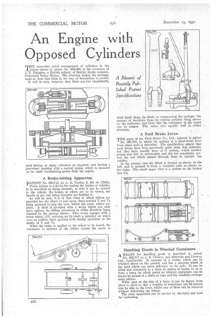
THE somewhat novel arrangement of cylinders in the engine shown in patent No. 360,496, is the invention of J. F. Edington, a British subject, of Sentul, Kuala Lumpur, Federated Malay States. The drawing makes the arrangement so clear that little in the way of description is needed.
It will be seen, however, that there are two crankshafts, each having as many cylinders as required, and having a gearwheel meshing with a central pinion which is mounted on the shaft transmitting power from the engine.
A Brake-tating Apparatus.
PATENT No. 360,711, by A. G. Taylor, 5, Bd. de Clichy,
Paris, relates to a device for testing the brakes of vehicles. It is described as being portable, so that it can be carried to the vehicle, the brakes of which are to be tested, the handle at one end being intended for holding it.
As will be seen, it is of that class in which rollers are provided for the wheel to rest upon, those marked 7 and 7a being serrated to grip the tyre, whilst the outer rollers are plain. A shaft is provided with a worm which can slide upon splines, its sliding movement in either direction being resisted by the springs shown. This worm engages with a worm wheel (15) carrying on its shaft a sprocket on which runs an endless chain gearing with similar sprockets on the shafts of 7 and 7a.
When the brake is applied to the wheel to be tested, the resistance to rotation of the rollers causes the worm to
wind itself along its shaft, so compressing the springs; the amount of deviation from, its central Position being shown by the indicator, and from this the resistance of the brake can be judged. The tester acts equally well in either direction.
A Ford Brake Lever.
THE name of the Ford Motor Co., Ltd., appears in patent
No. 360,787, in which the making of a hand-brake 'lever from sheet steel is described. The specification admits that such levers have been previously made from that material. but they have usually been of U section, which enabled grease and dirt to accumulate and did not completely protect the rod which passed through them fo operate the ratchet.
In the present ease the blank is formed as shown on the left, and is pressed to form a complete tube as shown on the right., The small upper view is a section on the broken line 2.2.