


New Two-stroke Oil Engines
Page 56
If you've noticed an error in this article please click here to report it so we can fix it.
Brief Details of a Range of Petters Power Units Having Three, Four or Six Cylinders
IN the oil-engine industry one of the best-known names is that of Petters, Ltd., Westland Works, Yeovil, and this concern has recently produced two-stroke-cycle models which are suitable for use in indukrial vehicles.
They are made in three shoes, that is, with three, four or six cylinders of 4-I ins, bore and 5f ins, stroke, giving respective capacities of 255 cubic ins., 340 cubic ins. and 510 cubic ins. In the same order, the torque developed is in the neighbourhood of 158 ft-lb.; 211 ft.-lb. and 316 ft.-lb. at the governed speed of 1,600 r.p.m. At this speed the brake mean effective pressure is 50 lb. per sq. in..
Complete with flywheel, dynamo and starter, but without oil or water, the weights of the three four and six-cylindered types are respectively 1,300 lb., 1,600 lb. and 2,250 lb. The two smaller types can be started by hand or by means of an electric motor, but, in the case of the six-cyliudered model, starting is only by motor. The height of the complete engine in each case is 3 ft. 1i in. and the overall width 2 ft. 21 ins., whilst the respective lengths are 3 ft. fti ins., 4 ft. 6i ins. and 5 ft. 101ins.
Aluminium is used for the crankcase, which is horizontally split. At the front end is the distribution drive, and there are two auxiliary shafts an the near side, one of which operates the Bosch injection pump and, in tandem therewith, the water pump, whilst the second shaft, which is below the first-mentioned one, drives the dynamo. In line with the last-named component is the starter, carried in a split tunnel.
B38
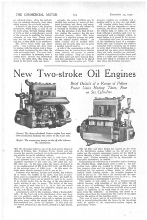
The oil filler and filter bodies are carried on the cover of the distribution casing, whilst on the off side of the engine are the separate seavengine-' pumps, air for which is drawn through a filter vertically disposed on the common *cover plate. Engine mounting can be by three-point or four-point attachment, as desired.
Surmounting the crankcase is a monobloc castieq forming the cylinder block. High-tensile steel is used f the connecting rods, which are coupled to Y-alloy p:.'' as, with four pressure rings and two scraper rings apiece. Steel is employed for the separate cylinder heads, in which are carried Bosch injector nozzles ; the injection pressure is '2,100 lb. per sq. in. The fuel is fed directly into the combustion chamber and the compression ratio is 14 to 1. For starting purposes a decompressor is provided.
This engine is well suited to use in a forward-control vehicle, because, with exception of the air filter, the off side is clear of auxiliaries; the scavenging pumps are not carried to a high level. The exhaust manifold gives a good degree of expansion at an early stage in the exit of the gases from the cylinders. In mounting this motor in a chassis, connections are required for the control of the pump and for the setting of the injection angle.
This type of power unit is of considerable interest ; it is held by several authorities that the future for the two-stroke cycle, as applied to •the compression-ignition engine, is particularly bright