


Patents Completed.
Page 20
If you've noticed an error in this article please click here to report it so we can fix it.
Complete specifications of the following patents will be sent to any address in the United Kingdom upon receipt of eightpence per copy at the Sale Branch, Patent Office, Holborn, W.C.
GEARBOX.—Searle and The L.G.O. Co., Ltd.—No. 5,455, dated 4th March, 1910.—According to this invention, a gearbox is arranged with chain-driven gears, except for the reverse. The form of gearbox described and illustrated is one in which the driving and driven shafts are co-axial, and the drive is trimsnutted through a layshaft. The chain wheel E is fixed to the end of the driving shaft, and surrounds the driven shaft ; it has an internal gear formed on it. This wheel E is coupled by a chain drive to the layshaft, which carries fixed on it two other chain wheels for forward speeds and one toothed gear for the reverse. These chain wheels are coupled to others loosely mounted on the driven shaft. Clutches (H and Hl) are arranged to couple the latter to the driven shaft by engagement with internal gears formed upon them. The gear wheel on the driven shaft for the reverse is attached to the clutch for the first speed.
TIRES. — Lane and Another. — No. 28,152, dated 2nd December, 1909.—This invention has reference to improvements in wheels for motors or other vehicles, of the kind in which a pneumatic cushioning ring is arranged to be out of contact with the road and yet to give a cushioning effect. Two pneumatic tires are arranged to a rim formed of two plates suitably shaped and arranged with a space between them to act as a guide for the outer rim. This is formed of two pressed-steel or other metal rings of Zsection, riveted together to form an external channel for the. rubber or other solid tire which forms the tread of the wheel, and also to form a web extending inwards towards the hub between the
pneumatic rings and into the guide formed in the inner rim. Means are provided for transmitting the drive from the hub to the outer rim without interfering with its movement. An alternative construction is also described and illustrated. NON-SKIDS. — Kahdemann. No.
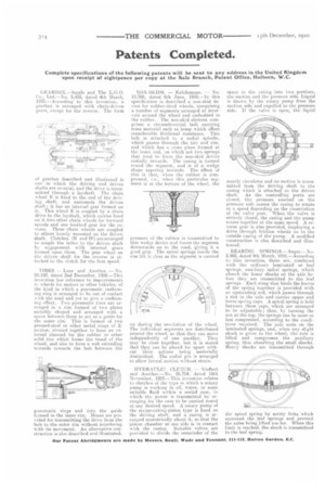
13,706, dated 6th June, 1910.—In this specification is described a non-skid device for rubber-tired wheels, comprising a number oi segments arranged at intervals around the wheel and embedded in the rubber. The non-skid element comprises a circumferential bolt carrying some material such as hemp which offers considerable frictional resistance. This bolt is attached to a radial spindle, which passes through the tire and rim, and which has a cross piece formed at. the inner end, on which act two springs that tend to force the non-skid device radially inwards. The casing is formed round the segment, and is of a wedge shape tapering inwards. The effect of this is that, when the rubber is compressed, i.e., when this particular segment is at the bottom of the wheel, the
pressure of the rubber is transmitted to this wedge device and forces the segment downwards on to the road, giving it a good grip. The spiral springs inside the rim lift it clear as the segment is carried rip during the revolution of the wheel. The individual segments are distributed around the wheel, so that they can move independently of one another. They may be close together, but it is stated that they can be placed far apart without their actions being materially diminished. The radial pin is arranged to allow lateral motion without strain.
HYDRAULIC CLUTCH. — Vintent and Another.—No. 26,754, dated 18th November, 1909.—This invention relates to clutches of the type in which a rotary pump is working in oil, water, or some suitable fluid within a sealed case, in which the power is transmitted by arranging for the ease to be carried round at any desired speed. A rotary pump of the reciprocating-piston type is fixed on the driving shaft, and a casing is arranged eccentrically about it, so that the piston chamber at one side is in contact with the casing. Suitable valves are provided to divide the remainder of the
space in the casing into two portions, the suction and the pressure side. Liquid is drawn by the rotary pump from the suction side and expelled to the pressure side. If the valve is open, the liquid
merely circulates and no motion is transmitted from the driving shaft to the casing which is attached to the driven shaft. As the controlling ports are closed, the pressure exerted on the pressure side Causes the casing to rotate at a speed depending on the constriction of the valve port. When the valve is entirely closed, the casing and the pump rotate together at the same speed. A reverse gear is also provided, employing a drive through friction wheels on to the outside casing of the pump. A modified construction is also described and illustrated.
BEARING SPRINGS.—Anger.---No. 5,460, dated 4th March, 1910.—According to this invention, there are, combined with the ordinary laminated or leaf springs, auxiliary spiral springs, which absorb the lesser shocks on the axle before they arc transmitted to the leaf springs. Each strap that. hinds the leaves of the spring together is provided with an upstanding rod, which passes through a slot in the axle and carries upper and lower spring caps. A spiral spring is held between these caps, which are arranged to be adjustable; thus, by turning the nut. at the top, the springs can be more or less compressed, according to the conditions required. The axle rests on the laminated springs, and, when any slight shock is given to the wheel, the axle is lifted and compresses the auxiliary spring, thus absorbing the small shocks. Heavy shucks are transmitted through the spiral spring by safety links which surround the leaf springs and prevent the as/es being lifted too far. When this limit is reached, the shock is transmitted to the leaf spring.