


Heating Arrangements for Coaches
Page 58
If you've noticed an error in this article please click here to report it so we can fix it.
CROM Daimler-Benz A.G., Stuttgart": Untertiirkheim, Germany, comes patent No. 674,502, which deals with a heating system for buses and coaches. The chief point of the patent is that the main radiator is used as the air hea ing element, the warmed air being directed inside or outside as circumstances require.
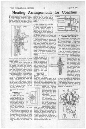
The drawing shows a plan view of part of the rear of a coach fitted with the scheme. The coach is of the rearengined type, the engine being shown at 1. The entrance door (2) is on the other side, the vehicle being, of course, for keep-to-the-right roads. The drive is taken via the gearbox (3) to a propeller-shaft (4) leading to the back axle.
A louvred air-inlet (5) has the radiator placed just behind it, the fan being driven by a long cross-shaft from the engine. The heated air when not required is discharged from a rear vent (6), but a two-way butterfly valve (7) can be turned so as to direct it into the passenger compartment; this_is the position shown in the drawing. The bulk of the apparatus is arranged to lie in the space under the rearmost seat.
TORSION-BAR • SPRINGS
PATENT No. 673,013. shows progress in torsion-bar design, the aim of which is to enable the , flexibility and characteristics of such a unit to be readily adjusted, without altering the torsion bar itself. The patentee IS George Salter and Co., Ltd., West Bromwich. •
The drawing shows a torsion bar built up from a pack of laminations (I). The bar is free at its ends for attachment to the suspension system, but at its middle it is fixed securely to the chassis by the clamp shown. Between the clamp and the bar is a split sleeve (2) and this unit forms the subject of the patent. By making the sleeve long or short, more or less of the bar can be rigidly held, so that the effective length of the bar can be easily chosen.
A NEW MAGNETIC CLUTCH
A MAGNETICALLY operated rt clutch forms the subject of patent No. 674,531 (Siper S.A., Tangier, North Africa). It is well known that the driven member of a clutch, if heavy, can make gearchanging difficult, and the aim of the present design is to reduce the inertia of this part to ' the smallest practicable value.
The annular magnet is made in two parts (1 and 2), leaving a gap between them. When energized, the magnet pulls itself towards the • flywheel in endeavouring to close this space. The magnet is permitted to slide slightly on its roller bearings (3) for this purpose. As the magnet moves towards the flywheel, it compresses the driven disc (4), which is of light construction, and splined on its shaft in the conventional manner.
In the scheme shown, a small air-gap (5) is present in the engaged position, but another design is mentioned in which the driven plate is made of thin magnetic material and is clamped tightly in the gap when the magnet is energized. Smo o th action • is one claim made.
MATCHING INJECTORS N an injection pump is being tested, it is customary to use a set of matched injectors for checking uniformity of delivery. But injectors themselves vary, and the adjusted pump may give irregular deliveries when used with the injectors on a particular engine. A scheme for obtaining some measure of certainty in these circumstances is shown in patent No. 671,940, by L. Hartridge, Tingewick Road, 673.013 • Buckingham.
The injector described Is provided with a sleeve
(1) surrounding t h e spring-loaded central rod and acting as an upward stop to the movement of the rod. The stop height can be adjusted by.turning a conically ended setscrew (2) which co-operates with a conical flange on the rod. As the lift of the pin is a factor determining output, matching of several injectors can be readily effecteR, provided that they are all tested by the same pump unit.
As a rough guide to the operator, a scale is provided on the front of the injector body, being read in conjunction with the tommy bar.
A MULTI-CYLINDERED TWOSTROKE OIL ENGINE A TWO-STROKE 'oil engine is dis PI closed in patent No. 674,532, by the Cooper-Bessemer Corporation, Mount. Vernon, Ohio, U.S.A. The patent deals only with certain improvements to the exhaust system, but the general design is also interesting.
The engi6e is of the V-type, and is shown in the drawing sectioned through a pair of cylinders. Charging air arrives from a common gallery and enters each cylinder through wall ports (1). The exhaust ports (2) are inwardly directed, and lead to a common central duct (3) which forms the basis of the patent. The duct completely obviates the need for complex manifolding, and occupies space otherwise unused.
The duct is • com pletely water-cooled, by the cylinders at the sides, and by a doublewalled jacket (4) at the top. A central baffle (5) directs the gases in an upward direction, and they leave by a pipe (6) in the top of the duct.
The system is particularly applicable to a two-stroke unit, in which the 'disposition of the exhaust ports greatly simplifies its application.