


A Powerful Cross-country Eight-wheeled Tractor
Page 33
Page 34
If you've noticed an error in this article please click here to report it so we can fix it.
ENJOYING a reputation for progressive design, Scammell Lorries, Ltd., Watford, may be regarded as a' leader in the production of vehicles incorporating unorthodox mechanisms, and built for the efficient performance of special duties, notably. but by no means exclusively, in the heaviest classes. When this company, therefore, develops a design—applicable to tractor or load carrier—for a machine for exceptionally heavy duty and suitable for cross-country conditions, one expects some
thing of special interest and ingenuity. • A layout far such a vehicle has now emerged from the Scammell drawing office and represents a combined effort on the parts of those two well-known engineers. Messrs. 0. D. North and P. G. Pugh. Outstanding features are that it drives and steeis on all eight wheels and that it can be powered by one, fwo,-three or four engines. A tractor incorporating four Gardner 6LW units would be a definitely powerful machine.
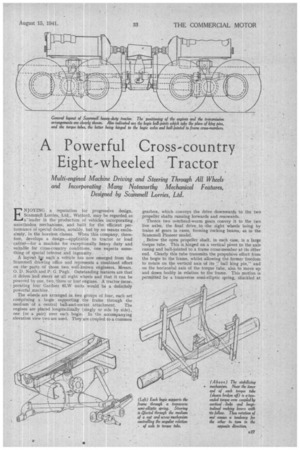
The wheels are arranged in two groups of four, each set comprising a bogie supporting the frame through the medium of a central ball-and-socket attachment. The engines are placed longitudinally (singly or side by side), one (or a pair) over each bogie. In the accompanying elevation view two are used. They are coupled to a common gearbox, which conveys the drive downwards to the two propeller shafts running forwards and rearwards.
Thence two overhead-worm gears convey it to the two live axles, the final drive to -the eight wheels being by trains of gears in cases, forming rocking beams, as in the Scammell Pioneer model.
Below -the open propeller shaft, in each case, is a large torque tube. This is hinged on a vertical pivot to the axle casing and hall-jointed to a frame cross-member at its Other end. Clearly this tube transmits the propulsive effort from the bogie to the frame, whilst allowing the former freedom to rotate on the vertical axis of its" ball king pin," and on the horizontal axis of the torque tube, also to move up and down bodily in relation to the 'frame. This motion is permitted by a transverse semi-elliptic spring, shackled at its ends to the frame and carrying' at its centre the ball joint. In addition, the wheel-carrying beams can rock on the axle,. whilst limited lateral movement of the bogie mid. point is allowed by the fact that the " king pin " is not immediately above the axle centre, but a short 'distance nearer to the centre of the vehicle.
In this connection, the .respective and relative positions of the various universal and hinge joints are interesting. Whilst the tarque-tube hinge pin and the propeller-shaft' second universal are, roughly, in vertical line, the bogie swivelling centre is between this lthe and the axis of the driving axle.
Associated with the positioning of these units is the steering layout. It will he ohserved that a-triangular structure, of which the axle is the base, has, at its apex, and suitably jointed thereto, a nut threaded on a transverse screw. Rotation of the last-named, which is effected through a system of shafts and gears by the steering wheel, causes the apex of the, triangle to describe an arc, of which the screw Is a tangent, and thus the whole bogie to be displaced angularly about its ball supporting member.
There is, of course, a nut and screw mechanism for each bogit and the two normally work in unison, the screws having opposite-hand threads, so that all wheels, when displaced, always have a common turning-circle centre. Perhaps the most interesting part of the design is the stabilizing asseinbly. Its object is, as it were, to provide that the two pairs of wheels on each side have a rocking motion corresponding to that of the wheels in any one pair. Considered in another manner, it imparts,an upward movement to the centre of the frame, on one side, when one pair of wheels is raised, a downward tendency being simultaneously transmitted to the other pair of wheels on the sai9,e side, as is also conveyed to. the other pair of wheels on the same axle.
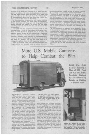
It will be observed by reference to the perspective sketch of the stabilizing mechanism that each torque tube carries a double-ended torque arm fixed to it just short of the point where it is spherically socketed to the frame central cross-member or saddle. Each end of each torque arm hangs by a link from, a longitudinal rocking beam pivoted above the frame. Accordingly, angular movement of one torque tube is transmitted by this system of arms and links to the other, • its direction being reversed on the way.
• This interesting chassis is dealt with fully in patent specification No. 537,619, obtainable from H.M. Stationery Office,